Page 3-11
Maintenance 3.10 - Hydraulic Pump
MX15/19
3.10 H
YDRAULIC
P
UMP
R
EMOVAL
NOTE: If the hydraulic tank has not been drained, plug the hoses to prevent excessive fluid loss.
Figure 3-15:
Hydraulic Pump
1. Mark, disconnect, and plug the hose
assemblies.
2. Loosen the capscrews and remove
the pump assembly from the motor.
I
NSTALLATION
1. Lubricate the pump shaft with general
purpose grease and attach the pump
to the motor with the capscrews.
2. Using a crisscross pattern, torque
each capscrew a little at a time until
all capscrews are torqued to 20 ft/lbs
(27 Nm).
3. Unplug and reconnect the hydraulic hoses.
4. Check the oil level in the hydraulic tank before operating the work platform.
3.11 H
YDRAULIC
D
RIVE
M
OTORS AND
H
UBS
R
EMOVAL
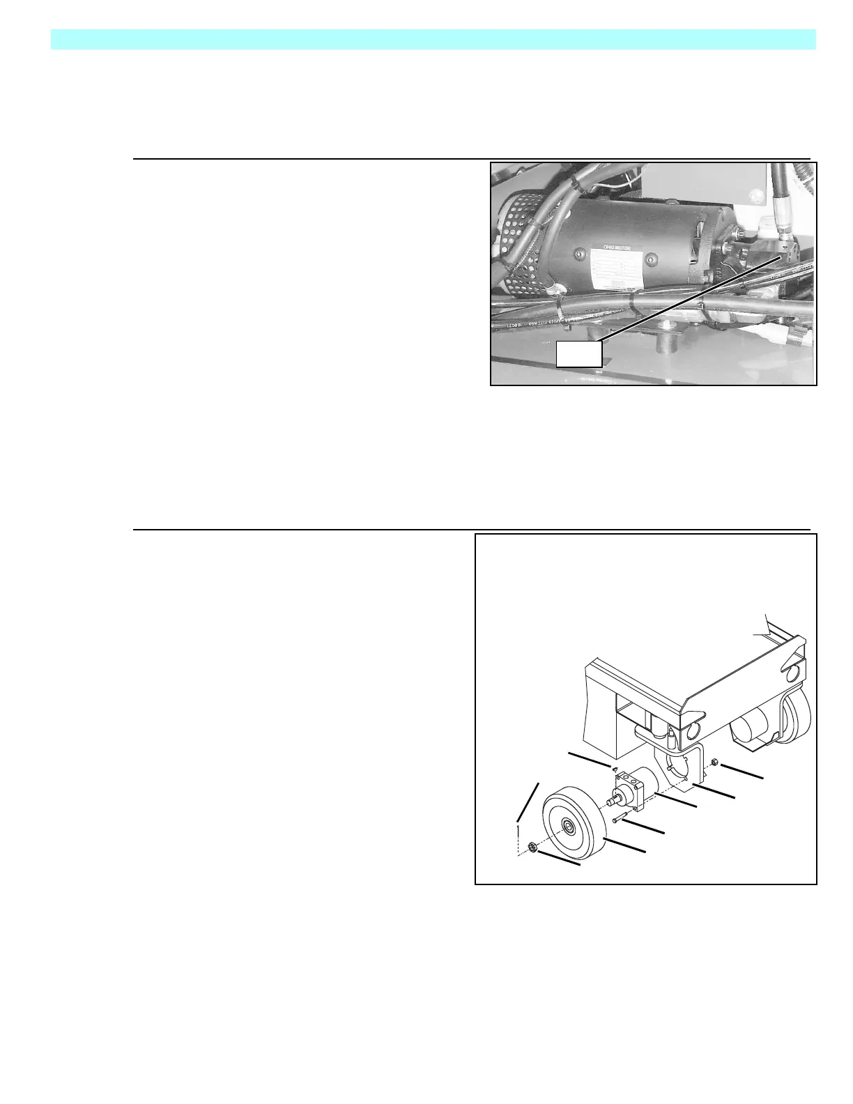
Figure 3-16:
Drive Motor Installation
1. Block the rear wheels to prevent
the machine from rolling.
2. Use a 1 ton (1000 kg) capacity jack
to raise the front of the machine.
Place two 1ton(1000kg)jack
stands under the machine.
Remove jack.
3. Remove the cotter pin, slotted nut,
wheel, and shaft key.
NOTE: Before disconnecting hoses,
thoroughly clean off all outside dirt around
fittings. (After disconnecting hoses and
before removing from vehicle,
IMMEDIATELY plug port holes.)
4. Tag, disconnect, and plug the hose
assemblies to prevent foreign
material from entering.
5. Remove the locknuts, capscrews,
and drive motor.
I
NSTALLATION
1. Position the drive motor in the wheel yoke and secure with capscrews and locknuts.
2. Install the shaft key, wheel, and slotted nut. Torque the slotted nut to 75 ft/lbs (102 Nm).
Install a new cotter pin. Do not back-off the nut to install the cotter pin.
3. Remove the plugs from the hose assemblies and connect to the drive motor.
4. Lift the platform with the jack and remove jack stands, then lower the jack and remove. Oper-
ate the drive system and check for leaks.
Pump
1. Drive Motor
2. Wheel Yoke
3. Wheel
4. Cotter Pin
5. Slotted Nut
6. Shaft Key
7. Capscrew
8.Locknut
2
8
1
7
3
5
4
6
 Loading...


