Page 4-4
Troubleshooting 4.4 - Measured Voltage at I/O Board
MX15/19
4.4 M
EASURED
V
OLTAGE AT
I/O B
OARD
Be sure that both the Platform and Chassis Emergency Stop Switches are pulled out to the ON
position.
All voltages are measured between the component and the B- terminal on the Motor Controller.
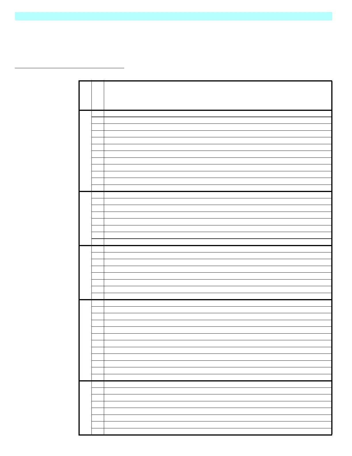
Table 4-2:
I/O Board Troubleshooting Table
CONNECTOR
PIN NUMBER
DESCRIPTION
J1
124Volts= Lift Mode Active / 0 Volts = Lift Mode Inactive
2 No Connection
324Volts= Drive Allowed / 0 Volts = Drive Not Allowed
4 24 Volts from Lower E-Stop / Lower E-Stop Not Depressed
524VoltsfromUpper E-Stop / Lower and Upper E-Stops Not Depressed
6 24 Volts Out to Interlock Lever when Upper Controls Selected & Upper/Lower E-Stops Not Depressed
7 No Connection
824Volts= Drive Forward or Lift Up/0Volts= Stop Drive Forward or Lift Up
924Volts= Drive Reverse or Lift Down / 0 Volts = Stop Reverse Drive or Lift Down
10 Accelerator Input / 20K Pot / 3.5 Volts to 0 Volts, Minimum to Maximum Speed
11 24 Volts = Steer Left / 0 Volts = Stop Steer Left
12 24 Volts = Steer Right / 0 Volts = Stop Steer Right.
J2
1 Goes to 0 Volts to Activate Depression Mechanism Extend Solenoid / 24 Volts = Solenoid OFF
2 No Connection
3 24 Volt Supply for Solenoids
4 Goes to 0 Volts to Activate Forward Solenoid / 24 Volts = Solenoid OFF
5 Goes to 0 Volts to Activate Reverse Solenoid / 24 Volts = Solenoid OFF
6 Goesto0VoltstoActivateLiftUp Solenoid / 24 Volts = Solenoid OFF
7 Goes to 0 Volts to Activate Steer Left Solenoid / 24 Volts = Solenoid OFF
8 Goes to 0 Volts to Activate Steer Right Solenoid / 24 Volts = Solenoid OFF
J3
1 Goesto0VoltstoActivateAlarm/24Volts= Alarm OFF
224Volts= Tilt Inactive / 0 Volts = Tilt Active
3 24 Volt Supply for Alarm, Tilt Sensor, Lift Down and Depression Mechanism Retract Solenoids
424Volts= Below Height Limit / 0 Volts = Above Height Limit
5 Goes to 0 Volts to Activate Lift Down Solenoid / 24 Volts = Solenoid OFF
6 Goes to 0 Volts to Activate Depression Mechanism Solenoid / 24 Volts = Solenoid OFF
724Volts= High Speed Active / 0 Volts = Low Speed Active
8 Battery Negative Supply for Tilt Sensor
J4
1 Goes to 0 Volts to Activate Line Contactor / 24 Volts = Line Contactor OFF
2 Supplies 24 Volts to Upper Control / Lower Control Switch
324Volts= Lower Control Mode
4 Supplies 24 Volts to Ground Lift Switch when in Lower Control Mode
5 24 Volt Supply Output
6 Goes to 0 Volts to Activate Hour Meter / 24 Volts = Hour Meter Not Activated
724Volts= Lift UpfromGroundControl/0Volts= Lift UpOFF
824Volts= Lift Down from Ground Control / 0 Volts = Lift Down OFF
9 24 Volt Supply Input from Battery via Lower E-Stop / Lower E-Stop Not Depressed
10 24 Volts from Upper Control Switch / 24 Volts =Upper Control Mode
11 Battery Negative Input to I/O Board
12 24 Volt Supply for Hour Meter and Line Contactor
J5
1 24VoltspowertoPin1ofSC1000(Key ON Power)
224Volts= Command Controller to Drive / 0 Volts = Stop Controller Drive
324Volts= Command Controller to Steer / 0 Volts = Steer OFF
424Volts= Command Controller to Lift / 0 Volts = Stop Lift
524Volts= Command Normal Speed / 0 Volts = Command Speed Cutback
624Volts= Line Contactor OFF / 0 Volts = Line Contactor ON
724Volts= No Direction Solenoid Allowed / 0 Volts = Direction Solenoid Allowed to Activate
8 Accelerator 3.5 Volts to 0 Volts / Minimum to Maximum Speed
 Loading...


