Page 3-3
Maintenance 3.4 - UpRight Connectors
MX15/19
from the Male Connector. Care should be taken that the Silicon Gasket is not damaged
during this procedure.
3. Check all parts for damage. Replace all parts which are damaged or worn.
4. Replace or recrimp the wires and contacts. Refer to “Crimping” procedure.
F
EMALE
C
ONNECTOR
(R
ECEPTACLE
)
1. Disconnect the male connector (plug) from the female connector (receptacle).
2. Using the notched end of the Removal Tool (or a wire hook), pull the Locking Wedge from
the Female Connector.
3. Check all parts for damage. Replace all parts which are damaged or worn.
4. Replace or recrimp the wires and contacts. Refer to “Crimping” procedure.
R
ELEASING
L
OCKING
F
INGERS
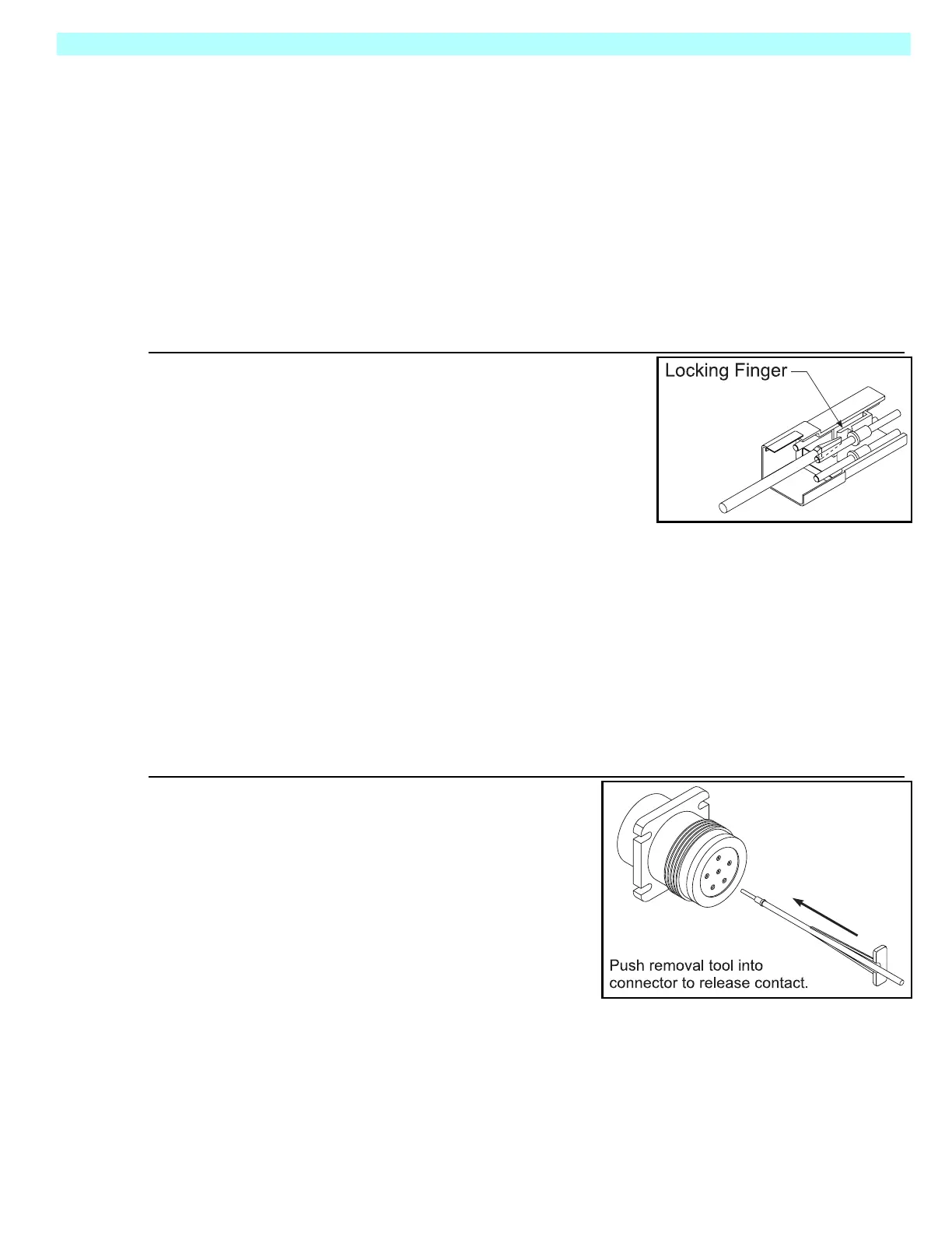
Figure 3-3:
Locking Finger, UpRight Connector
1. The Locking Fingers can be released following the
removal of the Locking Wedge of either the male or
female connector.
2. Use the removal tool (or flat blade screwdriver) to
push the Locking Fingers aside. This will release the
grip on the contact.
3. Pull the wire and contact out of the connector.
C
RIMPING
1. Strip .25inch(6mm) from the wire.
NOTE: Complete crimping instructions are included in each Field Kit.
2. Insert the contact into the crimping tool.
3. Insert the stripped wire into the contact. Copper strands should be visible in the bleed hole of
the contact and no copper strands should be loose (outside) of the contact barrel.
4. Completely close the handles of the crimping tool. Release the handles of the crimping tool
and remove the crimped contact.
5. Inspect the crimped contact to ensure that all strands are secure in the crimp barrel.
R
EMOVING
C
ONTACT FROM
H
EAVY
D
UTY
P
LUG
Figure 3-4:
Heavy Duty UpRight Connector
1. Slip the removal tool along the wire to be
replaced.
2. Push the removal tool into the connector until
the contact is released.
3. Pull the wire and contact out of the plug.
 Loading...


