Page 3-7
Maintenance 3.7 - Switch Adjustments
MX15/19
3.7 S
WITCH
A
DJUSTMENTS
L
EVEL
S
ENSOR
INTRODUCTION
The Level Sensor has three wires: red-power (24 v in), black-ground, white-output (24 v out). To
verify that the sensor is working properly, there is one LED under the sensor that indicates the
sensor is off level.
Figure 3-7:
Level Sensor
ADJUSTMENT
1. Place the machine on a firm level surface ± ¼°.
2. Use the Inclinometer (P/N: 10119-000-00) to
ensure front and rear of chassis is level ± ¼°.
3. Adjust the three leveling locknuts until the bub-
ble is centered in the circle on the attached
bubble level.
TEST
Raise the platform approximately 7 feet, then push
the level sensor to the side. The red LED should turn
on, and the tilt alarm should sound.
D
OWN
L
IMIT
S
WITCH
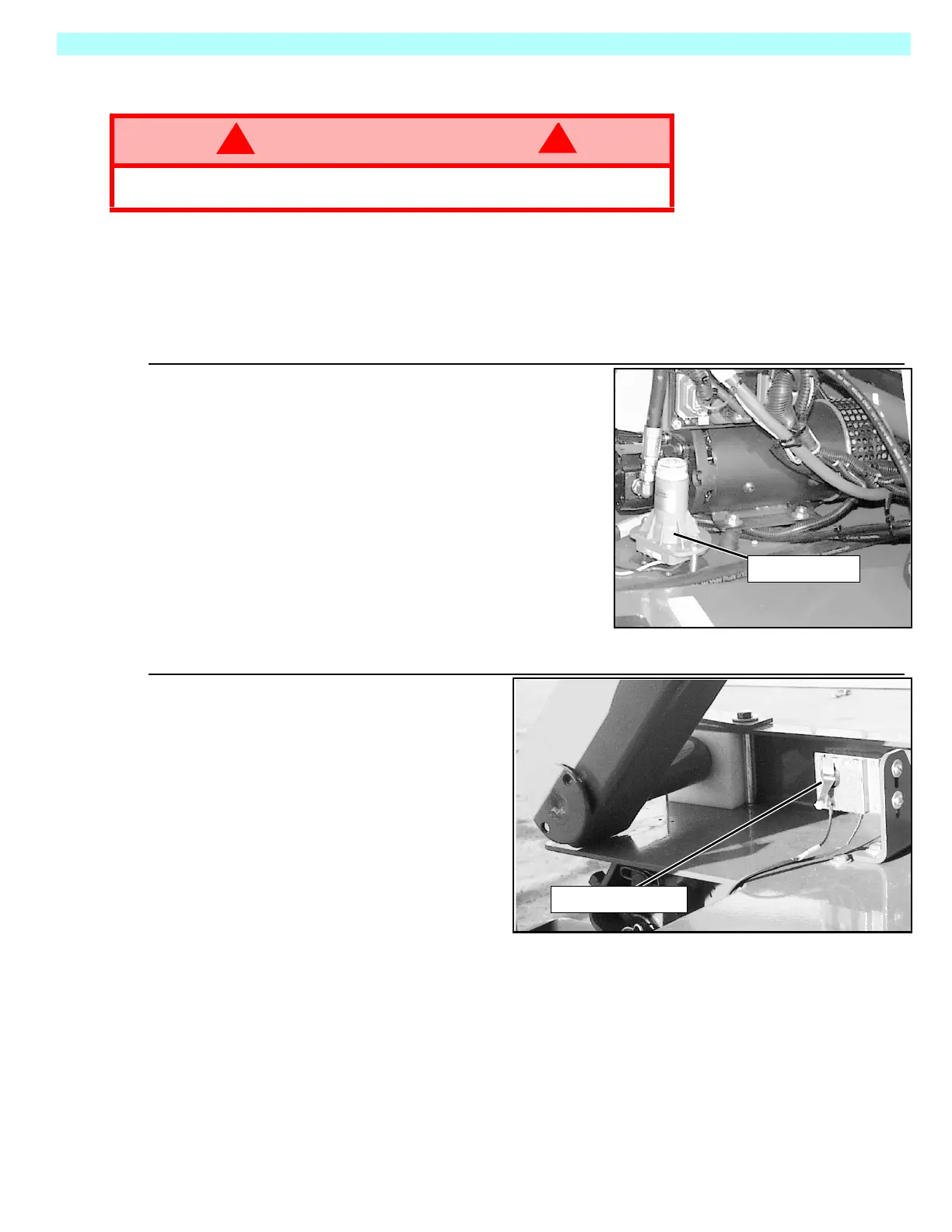
Figure 3-8:
Down Limit Switch
The Down Limit Switch cuts power to
the High Speed Circuit and supplies
power to the Level Sensor Circuit
when the platform is elevated.The
switch is located on the left side of
the chassis at the rear of the
machine.
The down limit adjustment for MX15
is 35 inches (89cm); 45 inches
(114cm) for the MX19.
No adjustment of the switch should
be necessary.
WARNING
!
!
Always use the elevating assembly brace whenever it is necessary to enter
the elevating assembly when the platform is elevated.
Level Sensor
Down Limit Switch
 Loading...


