Page 3-13
Maintenance 3.12 - Hydraulic Pressure Settings
MX15/19
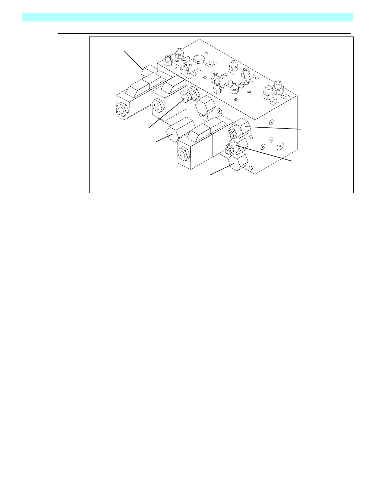
Figure 3-17:
Hydraulic Manifold Test Ports, from right side
C
OUNTERBALANCE
V
ALVES
1. Operate the work platform for 10-15 minutes to bring the hydraulic oil up to normal operating
temperature.
2. Remove test port cap and install the pressure gauge assembly.
3. Lift the work platform and block front wheels off the ground.
4. Loosen the locknuts on Counterbalance Valves.
5. With the Chassis Key Switch on DECK and the Drive/Lift Switch in DRIVE, depress the Inter-
lock Lever and slowly pull the Control Lever to REVERSE to drive the wheels.
6. Adjust the Forward Counterbalance Valve by turning the adjustment screw until the pressure
gauge indicates 800 psi (55 bar).
7. Slowly push the Control Lever to FORWARD to drive the wheels.
8. Adjust the Reverse Counterbalance Valve by turning the adjustment screw until the pressure
gauge indicates 800 psi (55 bar).
9. Check the settings by slowly moving the Control Lever FORWARD, then REVERSE, check-
ing the gauge to ensure pressures are properly set. Readjust as needed.
10. Tighten locknuts on valves to 6ft/lbs(8Nm.). Remove blocks and lower the work platform to
the ground.
11. Remove the gauge from the gauge port and reinstall cap.
12. Check for proper operation of the drive system and brake.
REAR
BOTTOM
RIGHT
Forward
Counterbalance
Valve
Reverse
Counterbalance
Valves
Lift Relief
Valve
Main Relief
Valve
Tes t Por t
Steering Relief
Valve
 Loading...


