28
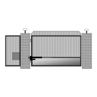
J2 Terminal Description
The accessory connector is a plug which can be
removed from the control board for ease of wiring
and troubleshooting purposes.
Place nger below connector and pull out to remove.
Terminal
1
+12 vdc Output
(Maximum current output 1.5 amp - 1500 milliamps)
2
Common Ground Input
-12 vdc
3
Push Button Input (normally open contacts)
(Push button, radio control, keypad, etc.)
4
Open Safety Edge (normally open contacts)
(Stops gate when opening)
5
Close Input (normally open contacts)
6
Secondary Entrapment Input (normally open contacts)
7
Common Ground Input
-12 vdc
8
Stop Circuit Input (normally closed contacts)
*DS1 switch #8 must be on for stop circuit function to be enabled.
9
Free Exit / Open Input (normally open contacts)
Loop input or any hold open input such as a 7-day timer, telephone access
unit, or maintain contact switch (normally open contacts). These devices
open the gate and will prevent the gate from closing if the contact is
maintained. Once the contacts have been released, the gate can be closed
with a closed signal device or the automatic close timer feature. Receiver
relay2 pre-wired for latching open.
10
Center Loop or Under Gate Loop Input (normally open contacts)
11
Safety Loop / Photo-eye / Reversing Edge Input
(normally open contacts)
12
Motion Detector Input (normally open contacts)
Stops a closed gate from opening. Active on closed limit only. *DS2 switch
must be on for Motion Detector function to be enabled.
J2 Terminal