Do you have a question about the Utax CD 1018 and is the answer not in the manual?
| Brand | Utax |
|---|---|
| Model | CD 1018 |
| Category | All in One Printer |
| Language | English |
Explains DANGER, WARNING, and CAUTION levels for user safety.
Describes various warning symbols used throughout the manual.
Guidelines for safe power connection and grounding to prevent shock.
Advice on placement, humidity, dust, and handling to ensure safety.
Essential safety steps before and during maintenance procedures.
Precautions for optical units, charger sections, and fixing sections.
Details on type, copying system, originals, paper capacity, and dimensions.
Information on printing speed, resolution, and scanning capabilities.
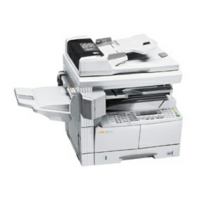
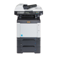
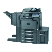
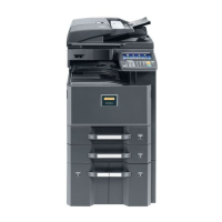
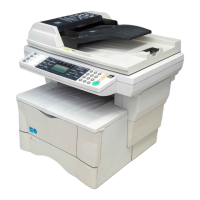
Identification of key physical parts of the main machine unit.
Identification and function of control keys and indicators on the operation panel.
Guidelines for handling and storing the drum to prevent damage.
Specifies temperature, humidity, power, and environmental conditions for installation.
Outlines the basic procedure from unpacking to making test copies.
Procedure for connecting the machine to a network.
Instructions for connecting the printer via parallel or USB cable.
Step-by-step guide for attaching the optional document processor.
Procedure for installing expansion memory modules (DIMM).
Steps to install the fax system assembly and connect it.
Describes how to access and run specific maintenance functions.
Lists maintenance items categorized by function (General, Optical, etc.).
Explains how to output current settings and event logs.
Covers initializing data, print timing, paper slack, and scanner input properties.
Details adjustments for scanner magnification and leading edge registration.
Adjusting fusing temperature and resetting fusing section problem data.
Describes how to access and perform system settings.
Configuring message display, language, and default operation modes.
Setting units of measurement and adjusting copy exposure for quality modes.
Covers settings like black-line correction, photo processing, and toner status.
Describes how to access and perform service settings.
Instructions for printing status pages containing machine settings and cumulatives.
Explains how misfeeds are indicated and how to remove jammed paper.
Details the conditions under which paper misfeeds are detected by sensors.
Lists jam codes and the specific conditions that trigger them.
Troubleshooting steps for jams in the conveying, fusing, and exit sections.
Troubleshooting for misfeeds related to the MP tray paper feed.
Troubleshooting for original jams within the Document Processor.
Explains the self-diagnostic codes and their corresponding causes and corrective measures.
Overview of various image quality issues, such as no image, light image, or lines.
Diagnosing why the machine doesn't operate or the main motor fails.
Addressing no paper feed, scanner travel, and multiple sheet feeding problems.
Troubleshooting steps for paper jams and abnormal noises.
Essential safety guidelines before starting assembly or disassembly.
Step-by-step instructions for safely removing the process unit.
Instructions for removing the front top cover and rear cover.
Steps for removing the right and left side covers of the machine.
Instructions on how to remove the feed roller from the machine.
Instructions for removing and refitting the transfer roller.
Steps to remove the engine PWB and transfer EEPROM.
Instructions for removing the main PWB and its associated shield.
Steps to remove the power supply and high voltage PWBs.
Instructions for removing the bias PWB from the machine.
Procedure for removing the main motor and its associated drive unit.
Instructions for removing the MP, feed, and registration clutches.
Procedure for removing the fuser unit from the machine.
Instructions for removing the heater lamp from the fuser unit.
Instructions for removing the thermistor from the fuser unit.
Instructions for removing the press roller from the fuser unit.
Steps for removing the scanner unit and its PWB.
Procedure for removing the laser scanner unit and LSU shield.
Steps to remove the ISU unit and detach the scanner shaft.
Instructions for removing the inverter PWB and exposure lamp mount.
Steps for removing the scanner motor and its belt.
Procedure to adjust leading edge registration for copy images.
Steps to adjust the center line of the printed image.
Procedure to adjust image magnification in the main scanning direction.
Procedure to adjust image magnification in the auxiliary scanning direction.
Procedure to correct errors in scanner leading edge registration.
Steps to adjust the scanner's center line for accurate image placement.
Procedure for adjusting scan margins when using the contact glass.
How to adjust image magnification when using the document processor.
Procedure to correct errors in DP leading edge registration.
Procedure to correct errors in DP trailing edge registration.
Steps to adjust the DP center line for accurate image placement.
Procedure for adjusting scan margins when using the document processor.
Instructions for upgrading firmware using a Compact Flash card.
Steps for replacing the DIMM module in the machine.
Diagram showing the paper path and identification of feeding system components.
Diagram illustrating the interaction between sensors, rollers, and the engine PWB.
Overview of the scanner unit, its parts, and how it scans originals.
Explanation of the six steps in the machine's electrophotographic cycle.
Diagram showing the internal components and driving power train of the process unit.
Information on the OPC drum's properties and careful handling requirements.
Explains how the main charger unit charges the drum.
Describes how the laser beam scans the charged drum surface.
Identification and description of components within the laser scanner unit.
Describes how toner is applied to the drum to form a visible image.
Explains how toner is transferred from the drum to the paper.
Describes how the heat roller and press roller fuse toner onto the paper.
Diagram showing the location of main PWBs and components in the main unit.
Shows the connections and interfaces of the main PWB.
Illustrates the connections and signals for the engine PWB.
Shows the circuit responsible for controlling the eraser lamp.
Explains the circuit controlling the heater lamp's operation.
Shows the circuit responsible for controlling the polygon motor speed.
Illustrates the block diagram of the power supply unit.
Shows the circuit connections and signals for the bias PWB.
Illustrates the circuit connections and signals for the high voltage PWB.
Shows the connections and signals of the CCD PWB.
Illustrates the circuits for operator panel switches and LEDs.
Shows the connections and driver circuits for the scanner PWB.