ITALIANO
- 5 -
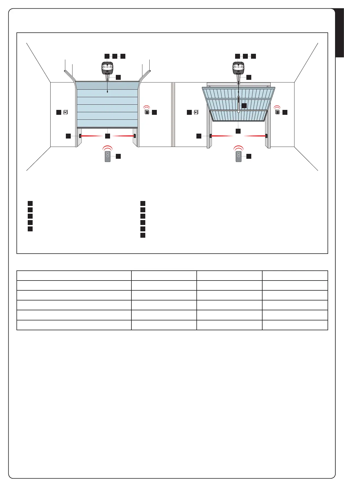
3 - SCHEMA DI INSTALLAZIONE
1 4 5
2
3
A D
C E
1 4 5
2
3
A D
F
B
E
A
B
C
D
E
F
1
2
3
4
5
Selettore chiave
Fotocellula interna
Fotocellula esterna
Selettore digitale via radio
Coste di sicurezza
Braccio adattatore per porte basculanti a contrappesi
Motore
Trasmettitore
Guida catena / cinghia
Centrale di comando
Modulo ricevitore
COMPONENTI ACCESSORI AGGIUNTIVI
LUNGHEZZA DEL CAVO < 10 metri da 10 a 20 metri da 20 a 30 metri
Alimentazione 230V 2 x 1,5 mm
2
2 x 1,5 mm
2
2 x 2,5 mm
2
Fotocellule (TX) 2 x 0,5 mm
2
2 x 0,5 mm
2
2 x 0,5 mm
2
Fotocellule (RX) 4 x 0,5 mm
2
4 x 0,5 mm
2
4 x 0,5 mm
2
Selettore chiave 2 x 0,5 mm
2
2 x 0,5 mm
2
2 x 0,5 mm
2
Costa di sicurezza 2 x 0,5 mm
2
2 x 0,5 mm
2
2 x 0,5 mm
2