ENGLISH
19
DECLARATION OF CONFORMITY
V
2 S.p.A. declares that the series of JET-24V actuators are in
conformity with the provisions of the following EC directives:
73/23/EEC electrical safety
9
3/68/EEC electromagnetic compatibility
99/05/EEC radio directive
98/37/EEC machine directive
N
ote: Declares that the above mentioned devices may not be
operated until the machine (automated gate) is identified, CE-
labeled, and declared to be compliant to the specifications of
Directive 89/392/EEC and following modifications.
The person in charge for the machine start-up must provide the
following records:
• Technical specification paper
• Declaration of conformity
• CE-labeling
• Testing record
• Maintenance record
• Operation manual and directions
Racconigi 10 / 09 / 2003
V2 S.p.A. legal representative
A. Livio Costamagna
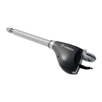
TECHNICAL SPECIFICATIONS
JET650 JET650-120V
Power supply 230VAC 50Hz 120VAC 60Hz
Average speed 120 mm /s 120 mm /s
Line absorption 1A 2A
Absorbed power 230W 240W
Full load current 8A
Working temperature -20 ÷ +50 °C
Max accessories load 24V 10W 10W
Protection fuses
F1 = 1,25A
DELAYED
F1 = 2A
Protection IP20
Rated Operating Time 4 minute
Motor weight 10 Kg
INDEX
DECLARATION OF CONFORMITY .............................................19
TECHNICAL SPECIFICATIONS....................................................19
IMPORTANT REMARKS.............................................................20
PRELIMINARY CHECKINGS.......................................................21
INSTALLATION LAYOUT ...........................................................21
U
SE LIMITS...............................................................................22
COMPOSITION .........................................................................24
ACCESSORIES ..........................................................................25
ASSEMBLY ...............................................................................25
INSTALLATION .........................................................................27
RELEASE FROM INSIDE .............................................................29
RELEASE FROM OUTSIDE .........................................................29
AUTOMATION RESTARTING.....................................................29
TERMINAL CONNECTIONS .......................................................30
PRGBCT - CONTROL UNIT FOR GARAGE DOOR .......................32
AUTOMATIC LEARNING...........................................................32
TRANSMITTER STORAGE BY MEANS OF A P1 KEY...................32
HOW TO MODIFY THE FUNCTIONING PARAMETER .................32
CURRENT SENSOR LEVEL .........................................................33
FUNCTIONING LOGIC...............................................................33
SLOWING DOWN, BLINKER AND WARNING LIGHT ..................34
PRE-FLASHING AND PHOTOCELL TEST .....................................34
FINAL CLOSING THRUST FORCE...............................................35
ROLLING CODE MODE.............................................................35
KEY START FUNCTION .............................................................35
COURTESY LIGHT AND BLINKER ..............................................35
NEW TRANSMITTER RADIO LEARNING.....................................35
TOTAL ERASING OF TRANSMITTER CODES ..............................35
ERROR SIGNALS.......................................................................35
SERVICE ...................................................................................35
PROBLEM SOLVING..................................................................36