ENGLISH
1 Mechanical safety rib (CMS)
2 Opening command to connect VRD (data input)
3
Opening command to connect traditional
devices having normally open contact
4 Stop command. Normally closed contact
5 - 8 - 11 Common (-)
6 Photocell. Normally closed contact
7
+24VDC 10W photocell (RX) power supply and
other accessories
9 +24VDC 10W blinker
10
Compulsory TX photocells power supply +24VDC
1W for check test
12 +24VDC 3W Pilot light
13 - 14 Power supply
15 Antenna gearbox
16 Antenna hearth brade
17 YELLOW: position sensor (level zero)
18 BLACK: position sensor (level zero)
19 RED: position sensor (level zero)
20 GREEN - 24VDC motor output
21 BROWN - 24VDC motor output
22 - 23 - 24 ENCODER
L1 Courtesy lamp model E14
31
CAUTION: UNUSED INPUTS THAT ARE NORMALLY
C
LOSED (CMS, STOP, PHOTOCELL) SHOULD BE CONNECTED
TO THE COMMON WIRE (-).
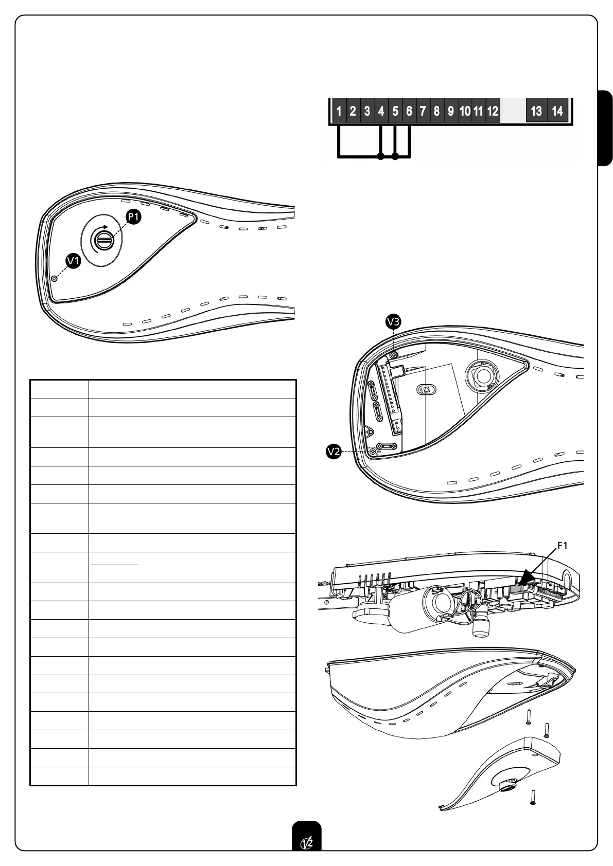
ELECTRIC CONNECTIONS
Carry out all the electrical connections with no voltage
• Unscrew the V1 screw
• Open the guard by turning at 90° the push-button P1.
• As far as the connections are concerned, please see the
paragraph “CONNECTIONS TO TERMINAL BOARD”, fixing the
cable output as the illustration explains.
FUSE REPLACEMENT
Carry out all the electrical connections with no voltage
1. Unscrew the V2 and V3 screws
2. Leave the cover of the motor
3. Replace the fuse F1 with one of the same value