ENGLISH
2 - INSTALLATION
2.1 Disassemble the door locking system and replace it with
the wire unlocking.
2.2 Measure the exact door half and trace some reference
points on the upper crosspiece and on the ceiling, in
order to make section bar positioning easier.
2.3 Fasten the front fastening group on the door upper
crosspiece or on the ceiling.
2.2 Insert slider, chain and actuator support bars into
the special section bar guide spaces.
2.3 Take the section bar guide to the ledge of the actuator
head.
2.4 Close both bolts V1 by means of their special nuts D1.
WARNING:
• Check the motor be firmly fixed onto the section.
• It is forbidden to use the motor if this doesn't match
perfectly with the section.
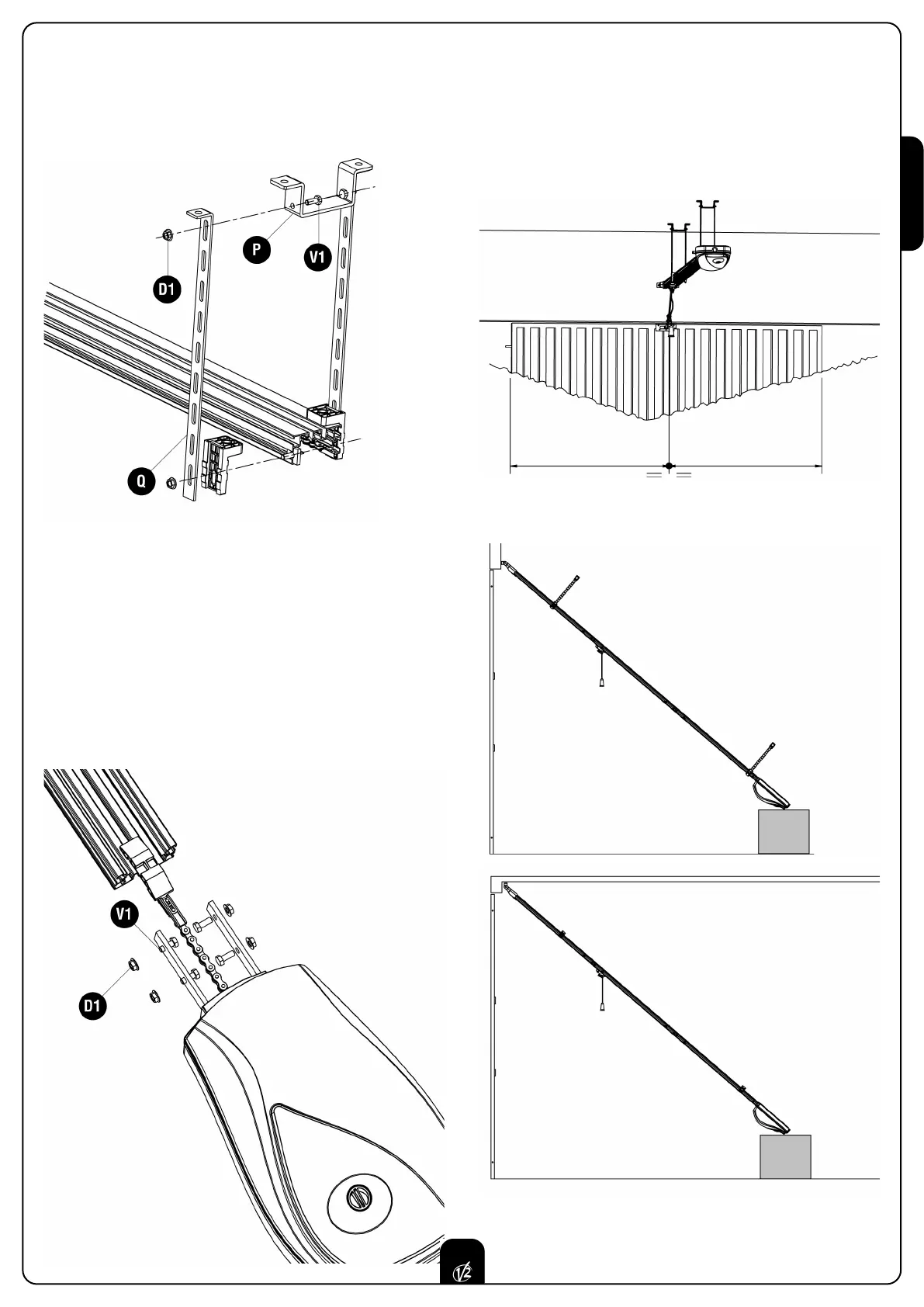
2.1 In case you need to lower the automation in height, make
use of the special drilled bars Q and bracket P.
WARNING: the maximum distance between the section
bar guide and the ceiling should not excede 300 mm.
27