ENGLISH
21
PRELIMINARY CHECKINGS
Before installing JET-24V, please check the following basic points:
• The door must be suitable to be automated (check the door
o
peration manual and directions). The door structure itself
must be stout and appropriate to be automated.
• Fix the engine steadily and using suitable material.
• If necessary, make the structural calculation and enclose to
the technical specification paper.
•
Check the door to be provided with anti-fall system
(independent of the suspension system)
• The door must be functional and safe.
• The door must open and close easily without any friction.
• The door must be properly balanced both before and after its
automation: stopping the door in any position, it must not
move (carry out a balance weight adjustment, if necessary).
• It is advisable to install the geared motor in the centre of the
door; it is permitted to move aside 100 mm to install the
sliding arm accessory J4 (see paragraph 2.6 page 28).
• In case of counterbalanced door, check that the minimum
distance between the track and the door must not be under
20 mm.
• If it is necessary to cut the section, the cut part must be
placed against the joint F (see paragraph 1.2 page 25)
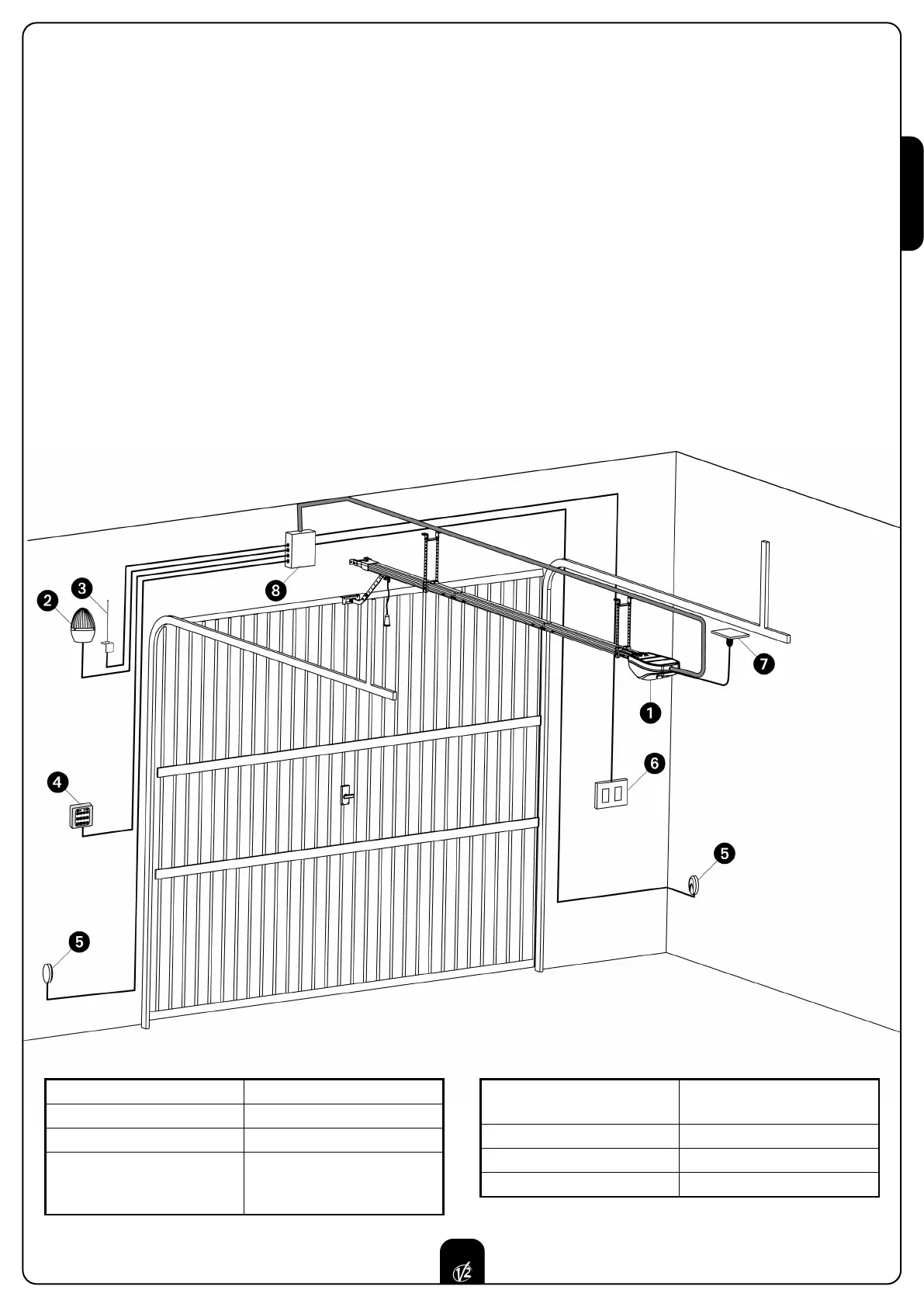
INSTALLATION LAYOUT
Photocells
cable 4 x 0,5 mm
2
(RX)
cable 2 x 0,5 mm
2
(TX)
Inside push-buttot panel
cable 3 x 1 mm
2
Schuco socket
-
Junction box
-
Actuator JET-24V
cable with plug 2 x 0.75 mm
2
Blinker
cable 2 x 0,5 mm
2
Aerial
cable RG-58
Key switch, digital keypad
and proximity reader
cable 2 x 0,5 mm
2