installation vacon
•
19
3
3.1.2 Cooling
Enough free space shall be left above and below the frequency converter to ensure
sufficient air circulation and cooling. You will find the required dimensions for free
space in the table below.
If several units are mounted above each other the required free space equals C + D
(see figure below). Moreover, the outlet air used for cooling by the lower unit must
be directed away from the air intake of the upper unit.
The amount of cooling air required is indicated below. Also make sure that the tem-
perature of the cooling air does not exceed the maximum ambient temperature of
the converter.
*. Min clearance A and B for drives for
MI1 ~ MI3 can be 0 mm if the ambient
temperature is below 40 degrees.
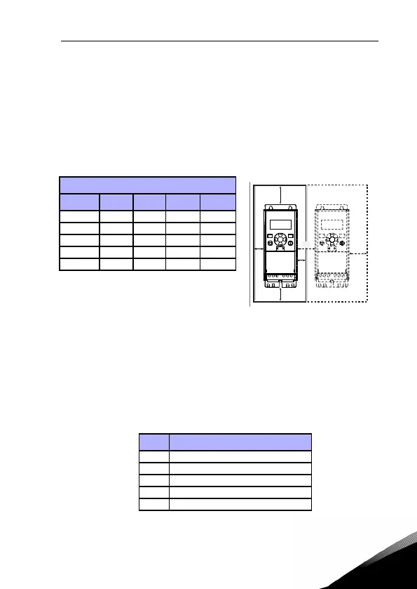
Figure 3.12: Installation space
A = clearance around the freq. converter (see also B)
B = distance from one frequency converter to another or distance to cabinet wall
C = free space above the frequency converter
D = free space underneath the frequency converter
NOTE! See the mounting dimensions on the back of the drive.
Leave free space for cooling above (100 mm), below (50 mm), and on the sides (20 mm)
of Vacon 20! (For MI1 - MI3, side-to-side installation allowed only if the ambient tem-
perature is below 40 °C; For MI4-MI5, side-to-side installation is not allowed.
Min clearance (mm)
Type A* B* C D
MI1 20 20 100 50
MI2 20 20 100 50
MI3 20 20 100 50
MI4 20 20 100 100
MI5 20 20 120 100
Table 3.4: Min. clearances around AC drive
Type Cooling air required (m³/h)
MI1 10
MI2 10
MI3 30
MI4 45
MI5 75
Table 3.5: Required cooling air