4
vacon • 34 Active Front End (AFE)
Local contacts: http://drives.danfoss.com/danfoss-drives/local-contacts/
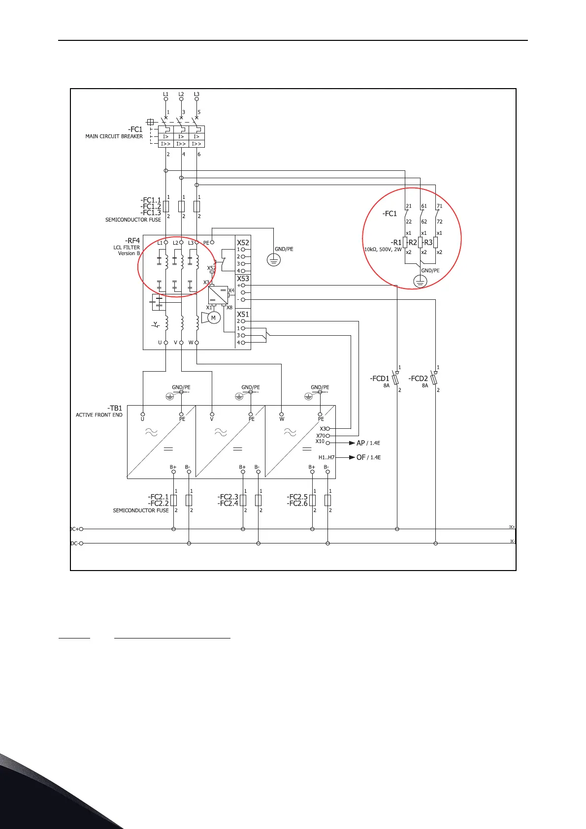
Figure 16. Wiring diagram of LCL and AFE circuit when used in installations which have earth fault
protection relay or when used in IT network or when AFE of other manufacturer is connected to same
transformer secondary supply
4.7.2.2
Removing HF capacitors
If a PWM modulated rectifier from another manufacturer is connected to the same input
transformer, the HF capacitor must be removed, because the HF capacitors will be filtering the high
frequency disturbances from another manufacturer’s active front ends. It is recommended to
always use own transformers if more than one manufacturer’s AFEs are used.
Figure 17 (for FI9 and FI10) and Figure 18 (for FI13) have a red marking on the lead that has to be
removed from each capacitor if the HF capacitors are not to be used. Removing the lead disconnects
the capacitors from ground potential.

 Loading...


