5
vacon • 52 Installation
Local contacts: http://drives.danfoss.com/danfoss-drives/local-contacts/
5. INSTALLATION
5.1 Mounting
The equipment mounting must be sturdy enough to carry the weight of the equipment. The
enclosure class of the equipment will depend on the mounting and solutions to be used. The
equipment mounting must provide sufficient shielding for contact of the live parts (IPXXB). The
installation and mounting must comply with local laws and regulations.
5.1.1 Active Front End Unit
The Active Front End can be mounted in a vertical position on the back plane of a cubicle. Enough
space must be reserved around the Active Front End to ensure sufficient cooling, see Figure 30.
Follow the minimum dimensions for installation, see Table 27. Required cooling air capacity and
minimum air holes on the switchgear, see Table 28. Also make sure that the mounting plane is
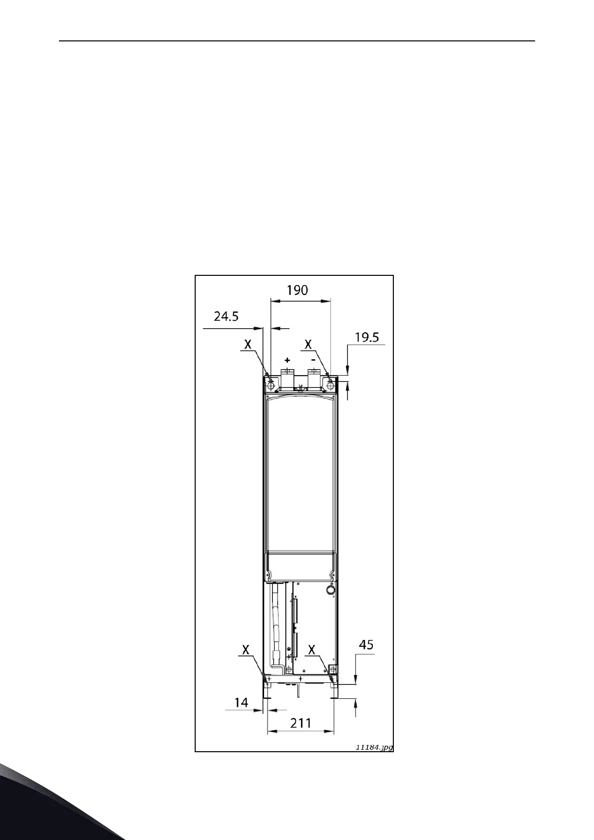
relatively even. The Active Front End is fixed with four bolts, Figure 23, Figure 24 and Figure 25.
Figure 23. Mounting points of FI9 AFE unit
 Loading...


