5
vacon • 56 Installation
Local contacts: http://drives.danfoss.com/danfoss-drives/local-contacts/
5.1.3 Control Box
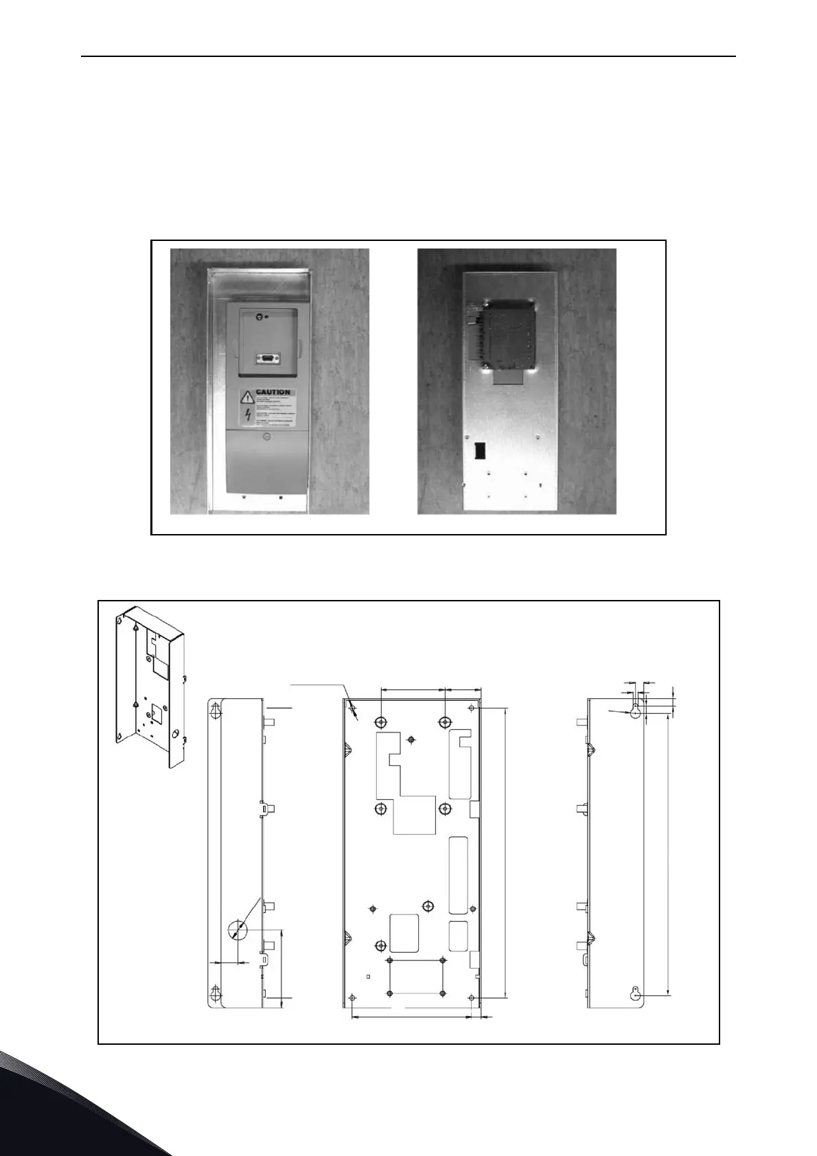
The control unit of the Active Front End unit is mounted into a mounting rack which then can be
placed inside the enclosure, Figure 28 and Figure 29. The control unit should be placed so that it is
easy to access. VACON
®
alpha-numeric or graphical keypad can be used to control the Active Front
End unit. The keypad is connected to the control unit. The keypad can be mounted on the enclosure
door with optional door mounting kit, see Appendix 85. In that case the keypad connects to the
control unit with an RS232 cable. Pay special attention to the grounding of the cable, see the
instructions below.
Figure 28. Control unit installed into the mounting box; Left: front; Right: back
Figure 29. Mounting points of Control Box
11187.emf
Ø
2
0
68
4 pcs Ø 5
38
308
10
R
5
8.5
300
5
82
18
126
7.5
8.5
 Loading...


