5
vacon • 76 Installation
Local contacts: http://drives.danfoss.com/danfoss-drives/local-contacts/
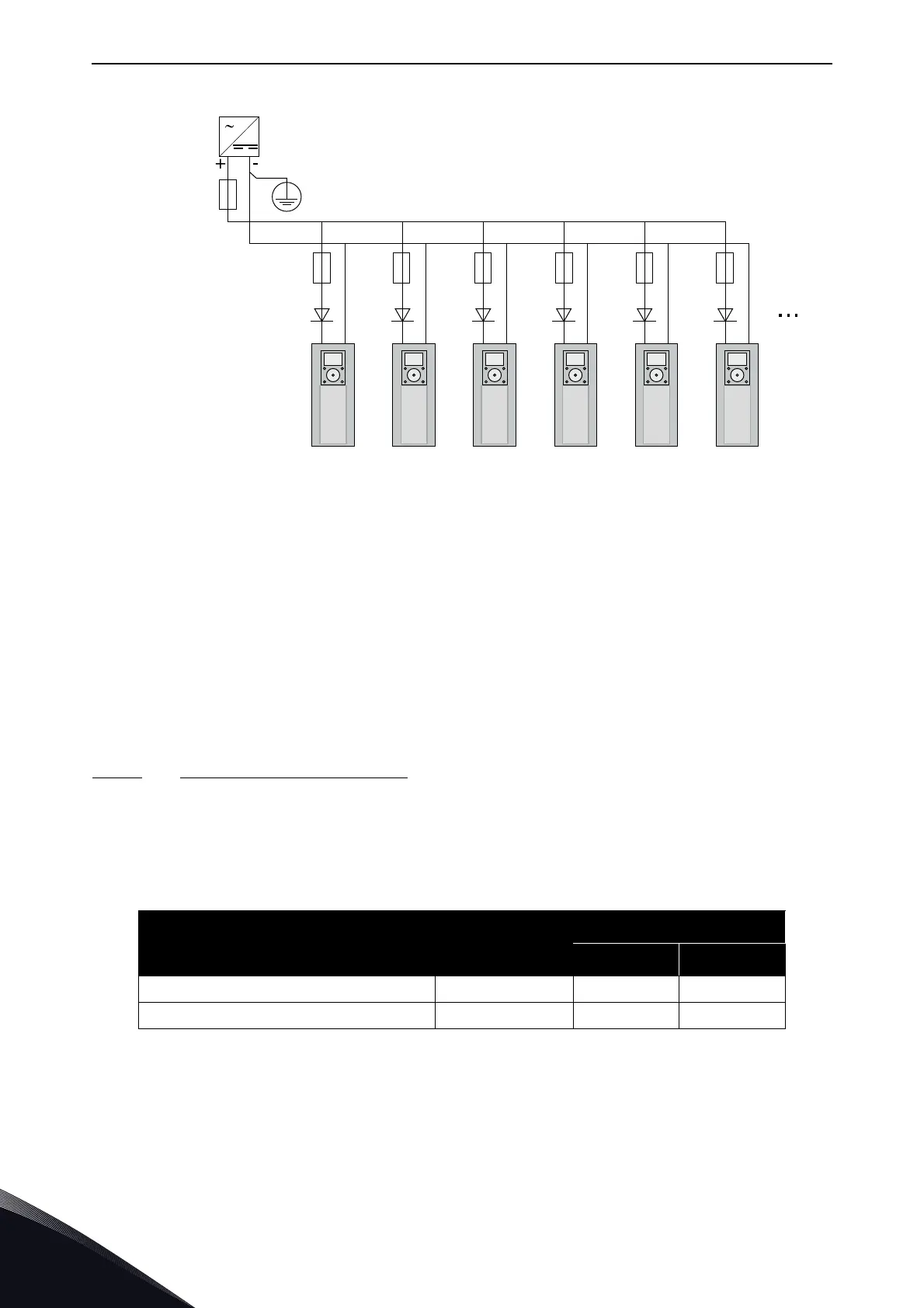
Figure 47. Parallel connection of 24 V inputs with many AC drives
NOTE! The control unit I/O ground is not isolated from the chassis ground / protective earth. In the
installation, take into account the potential differences between the grounding points. We
recommend that you use galvanic isolation in the I/O and 24V circuitry.
NOTE! Analogue outputs and inputs do not work with only +24V supplied to the control unit.
If there is a +24V/EXT+24V output on the board, it is locally short-circuit protected. If one of the +24V/
EXT+24V outputs short-circuits, the others remain powered because of the local protection.
5.4.3 Control unit cabling
The OPTA1 basic board has 20 control terminals, and the relay board has 6 or 7. You can see the
standard connections of the control unit and the descriptions of signals in Figure 48.
5.4.3.1
Selection of the control cables
The control cables must be a minimum of 0.5 mm
2
(20 AWG) screened multicore cables. The
terminal wires must be a maximum of 2.5 mm
2
(14 AWG) for the terminals of the relay board and
1.5 mm
2
(16 AWG) for other terminals.
Table 31. The tightening torques of the control cables
The terminal
The terminal
screw
The tightening torque
Nm lb-in.
Relay and thermistor terminals M3 0.5 4.5
Other terminals M2.6 0.2 1.8
PE/GND
-G1
Ext +24VDC
Power Supply
-F1
#6 #7 #6 #7 #6 #7 #6 #7 #6 #7 #6 #7
-F2
1A
gG/
Class CC
-Q1
3A
-Q2
3A
-Q3
3A
-Q4
3A
-Q5
3A
-Q6
3A
-F3
1A
gG/
Class CC
-F4
1A
gG/
Class CC
-F5
1A
gG/
Class CC
-F6
1A
gG/
Class CC
-F7
1A
gG/
Class CC
 Loading...


