6
vacon • 88 Control Keypad
Local contacts: http://drives.danfoss.com/danfoss-drives/local-contacts/
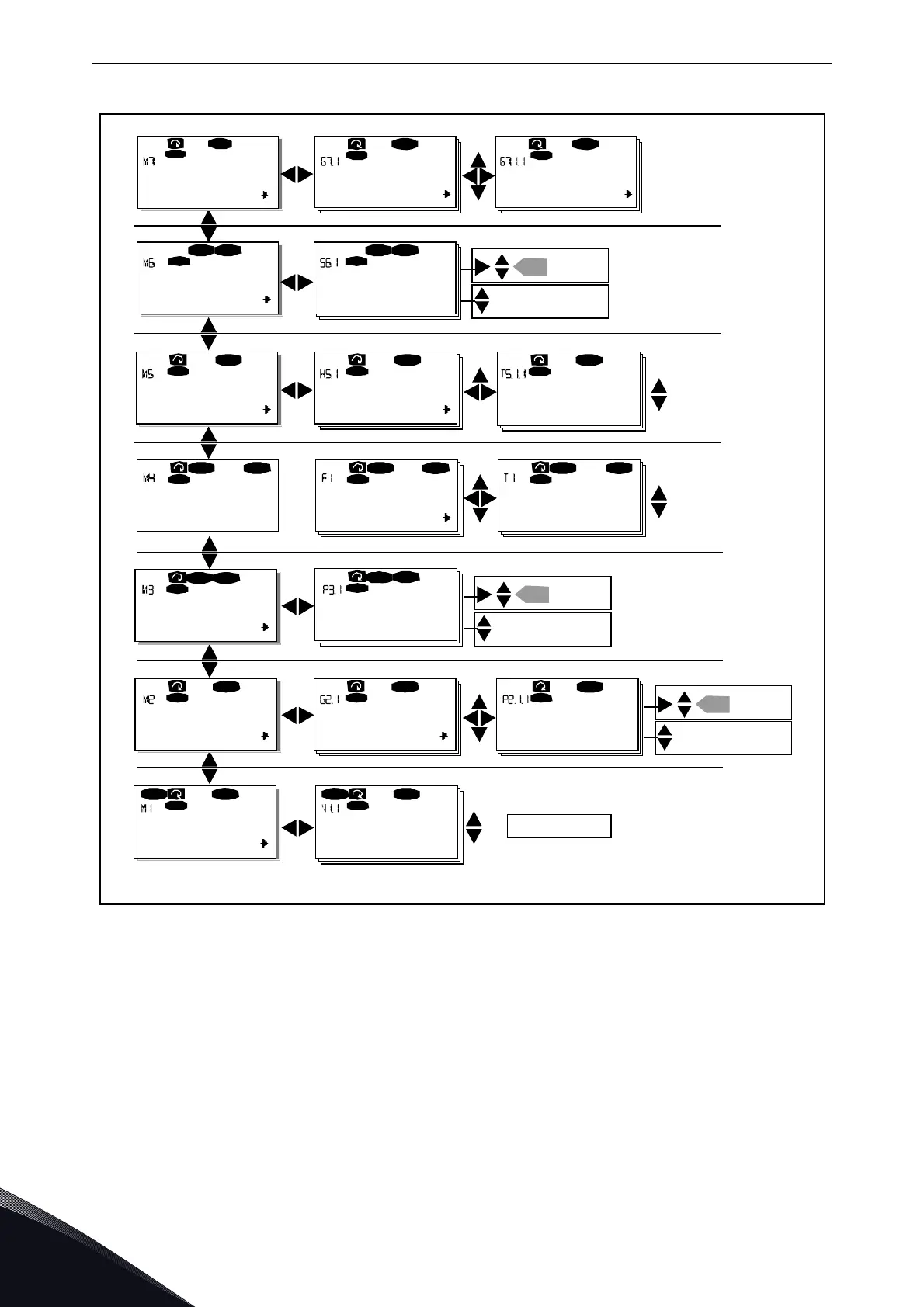
Figure 58. Keypad navigation chart
6.3.1 Monitoring menu (M1)
You can enter the Monitoring menu from the Main menu by pressing Menu button right when the
location indication M1 is visible on the first line of the display. Figure 59 shows how to browse
through the monitored values.
The monitored signals carry the indication V#.# and they are listed in Table 32. The values are
updated once every 0.3 seconds.
This menu is meant only for signal checking. The values cannot be altered here. For changing values
of parameters, see Chapter 6.3.2.
FT1
T7
STOP FAULT
I/Oterm
STOP
I/Oterm
FAULT
H1
H3
READY
I/Oterm
T1
T7
I/Oterm
READY
I/ O t er m
READY
S1
S9
STOP READY
I/Oterm
STOP READY
I/Oterm
enter
G1
G5
RE A D Y
I/Oterm
A:NXOPTA1
READY
I/Oterm
G1
G1
READY
I/ O t e r m
V1
V15
READY
I/Oterm
RUN
13.95 Hz
READY
I/Oterm
RUN
G1
G9
READY
I/Oterm
P1
P15
READY
I/Oterm
13.95 Hz
READY
Local
P1
P3
READY
I/Oterm
ST OP
READY
I/Oterm
ST OP
enter
enter
F0
STOP FAULT
I/Oterm
Parameters Basic parameters Min Frequency
1 1 Output phase O pera tio n day s
17
Fault his to ry 11 Out put phas e Ope rati on d ays
Sys tem Menu La nguage
Change
value
Browse
Expander boards
Parameters
P1
P3
Monitor Output frequency
No editing!
Keypad co ntrol
Con trol P lace
I/O Terminal
Change
value
Change
value
Browse
Browse
Active faults
17
English
or:
11205.emf
 Loading...


