EasyManuals Logo

Vacon NX series User Manual

Vacon NX series
122 pages
To Next Page IconTo Next Page
To Previous Page IconTo Previous Page
Page #51 background imageLoading...
Page #51 background image
Active Front End (AFE) vacon • 49
Local contacts: http://drives.danfoss.com/danfoss-drives/local-contacts/
4
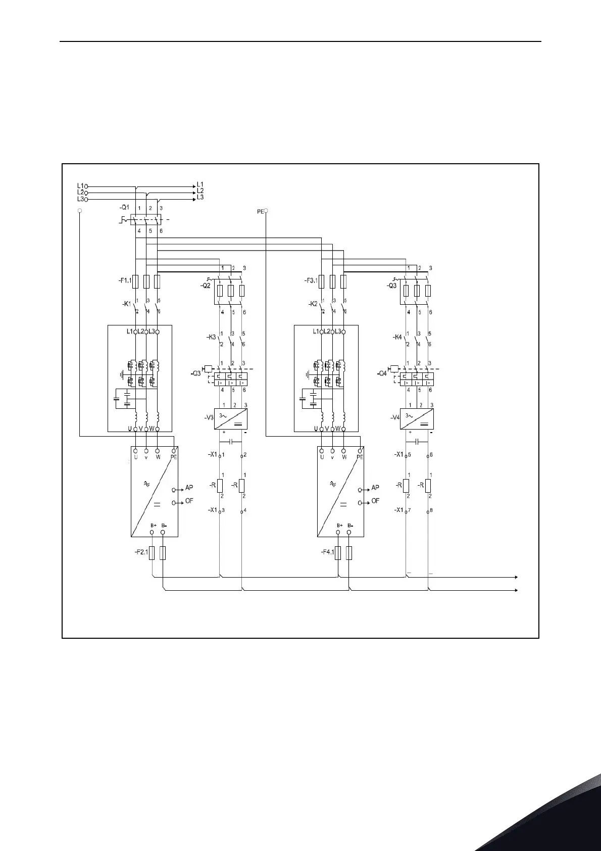
4.15.2 Each Active Front End unit has the pre-charging circuit
Each Active Front End can have its own pre-charging circuit. Each unit controls its own pre-charging
and main contactor. See Figure 20. One control switch can be used, but if an Active Front End unit
needs to be controlled independently, separate switches are needed. With this the system is more
redundant than with a common pre-charging circuit. The circuit diagram for control, see Appendix
74 and Appendix 76.
Figure 20. Active Front End units parallel connection with own pre-charging circuits
PE
+LCL-U1
+LCL-U2
11166.emf
+AFE-U1
NXA xxxx x
+AFE-U2
NXA xxxx x
DC+
DC-
Main Circuit
Double Insulated
Double Insulated
Double Insulated
Double Insulated

Table of Contents

Other manuals for Vacon NX series

Questions and Answers:

Question and Answer IconNeed help?

Do you have a question about the Vacon NX series and is the answer not in the manual?

Vacon NX series Specifications

General IconGeneral
Product typeAC Drive
Output voltage range0-Uin
Frequency range0-500 Hz
Enclosure classesIP00, IP21
Mounting typesWall
Braking chopperIntegrated or external
EMC filterBuilt-in or external
Control modesScalar, Vector
Protection featuresOvercurrent, overvoltage, undervoltage, overtemperature, short circuit
Communication optionsModbus, Profibus, CANopen, Ethernet
Ambient temperature range-10°C to +50°C
Cooling methodAir-cooled

Related product manuals