EasyManuals Logo

Vacon NX series User Manual

Vacon NX series
122 pages
To Next Page IconTo Next Page
To Previous Page IconTo Previous Page
Page #84 background imageLoading...
Page #84 background image
5
vacon • 82 Installation
Local contacts: http://drives.danfoss.com/danfoss-drives/local-contacts/
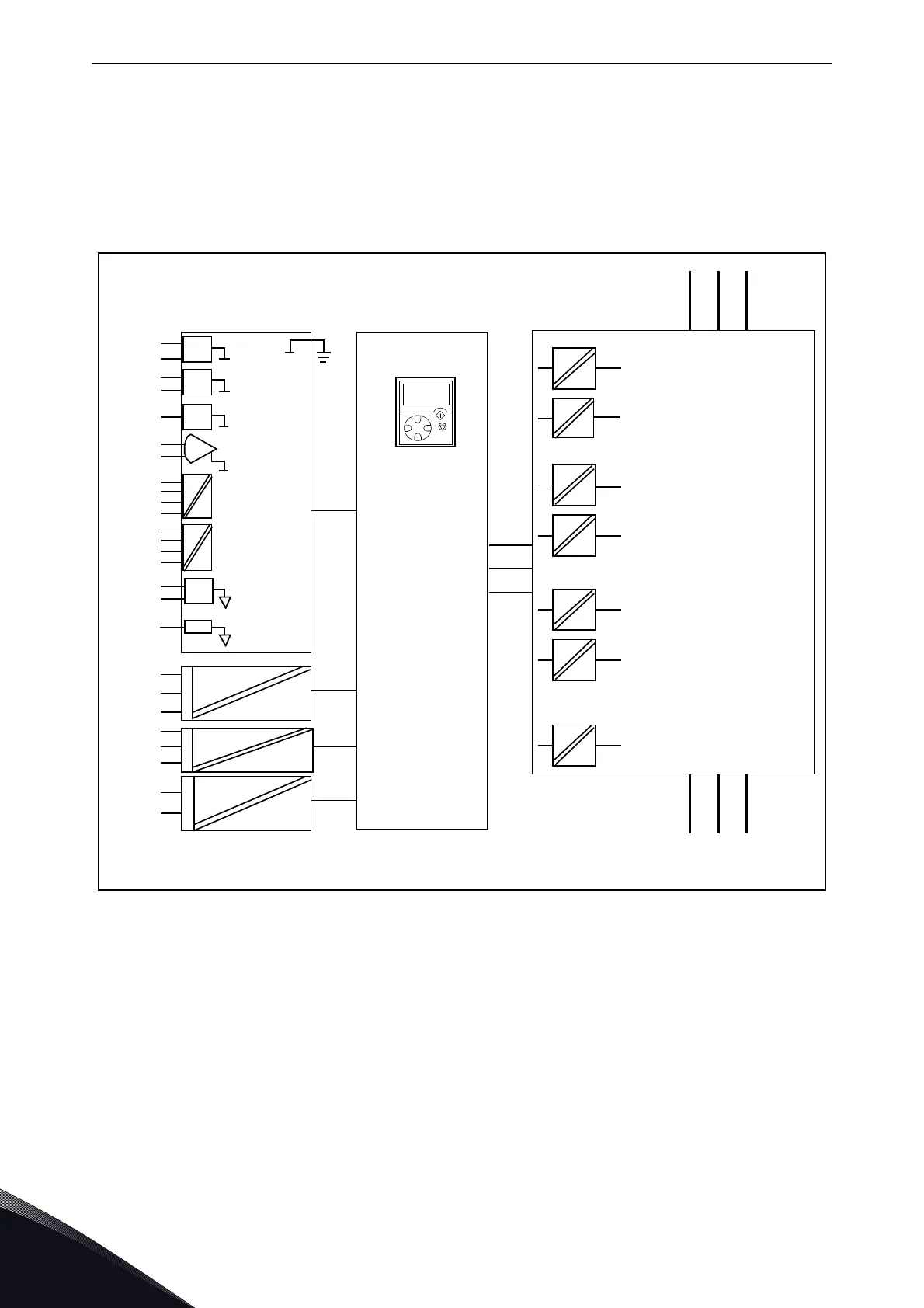
5.5 Galvanic isolation barriers
The control connections are isolated from the mains potential and the GND terminals are
permanently connected to ground. See Figure 55.
The digital inputs are galvanically isolated from the I/O ground. The relay outputs are additionally
double-isolated from each other at 300 VAC (EN-50178). See Figure 55.
Figure 55. Galvanic isolation barriers
L1 L2 L3
UVW
RO1/1
RO1/2
RO1/3
RO2/3
RO2/2
RO2/1
10Vref
GND
GND
+24V
AI1
AI2+
AI2 -
DIN1...
DIN3
CM A
DIN4...
DIN6
CM B
AO1+
AO2 -
DO1
n
k6_1 5
TI1+
TI1-
Control I/O
ground
Digital input
group A
Digital input
group B
Analogue
output
Digital
output
Control
board
Control
panel
Gat e drivers
Power
board
11209.emf

Table of Contents

Other manuals for Vacon NX series

Questions and Answers:

Question and Answer IconNeed help?

Do you have a question about the Vacon NX series and is the answer not in the manual?

Vacon NX series Specifications

General IconGeneral
Product typeAC Drive
Output voltage range0-Uin
Frequency range0-500 Hz
Enclosure classesIP00, IP21
Mounting typesWall
Braking chopperIntegrated or external
EMC filterBuilt-in or external
Control modesScalar, Vector
Protection featuresOvercurrent, overvoltage, undervoltage, overtemperature, short circuit
Communication optionsModbus, Profibus, CANopen, Ethernet
Ambient temperature range-10°C to +50°C
Cooling methodAir-cooled

Related product manuals