Installation vacon • 77
Local contacts: http://drives.danfoss.com/danfoss-drives/local-contacts/
5
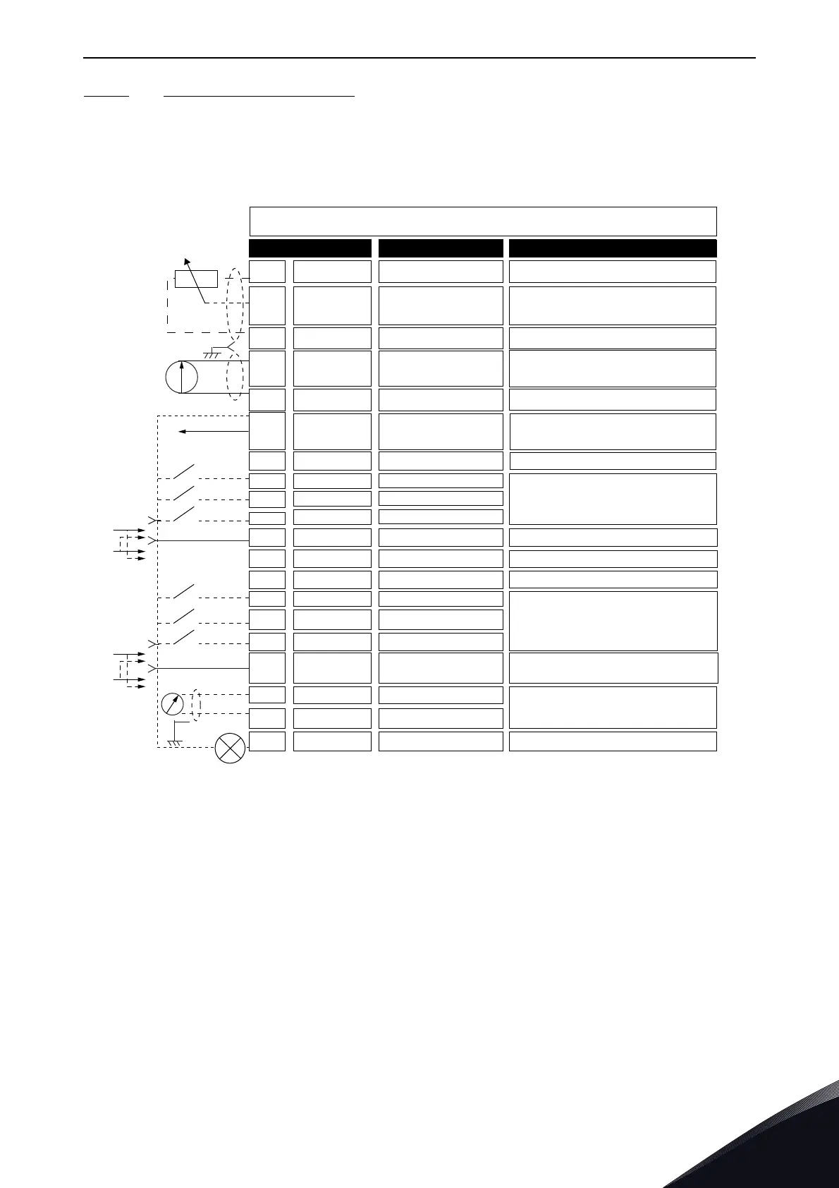
5.4.3.2 Control terminals on OPTA1
Here you see the basic description of the terminals of the I/O board and the relay board. For more
information, see Jumper selections on the OPTA1 basic board. For more information on control
terminals, see VACON
®
All in One Application manual.
Figure 48. The control terminal signals in OPTA1
*) See Fig. 26 Jumper blocks on OPTA1.
Parameter references for I/O on keypad and NCDrive are: An.IN:A.1, An.IN:A.2, DigIN:A.1, DigIN:A.2,
DigIN:A.3, DigIN:A.4, DigIN:A.5, DigIN:A.6, AnOUT:A.1 and DigOUT:A.1.
To use the control voltage output +24V/EXT+24V:
• you can wire the +24V control voltage to digital inputs through an external switch.
• you can use the control voltage to power up external equipment, such as encoders and
auxiliary relays.
Note that the specified total load on all available +24V/EXT+24V output terminals must not exceed
250mA. The maximum load on the +24V/EXT+24V output per board is 150mA.
1
6
2
3
4
5
18
19
20
12
7
13
8
9
10
14
15
16
11
17
Maximum current 10 mA
Differential input if not connected to ground
Allows ±20 V common mode voltage to GND
Ground for reference and controls
Same as terminal #7
Digital inputs can be disconnected from ground (*)
Must be connected to GND or 24 V of I/O term.
or to ext.24 V or GND
Selection with jumper block X3 (*)
Ri = min. 5 kΩ
18-30 V = 1
Ri = min. 5 kΩ
18-30 V = 1
Output signal range: Current 0(4)-20 mA,
RL max 500 Ω or
Voltage 0-10 V, RL >1kΩ
Selection with jumper block X6 (*)
Maximum Uin = 48 VDC
Maximum current = 50 mA
Open collector output
AO1-
DO1
+24V
GND
GND
DIN1
DIN2
DIN3
DIN4
DIN5
DIN6
CMA
CMB
Standard I/O board
Terminal Signal Description
+10V
ref
AI1+
GND/AI1-
AI2+
GND/AI2-
+24V
Reference voltage
Analogue input,
voltage or current
Analogue input,
voltage or current
24 V aux. voltage
I/O ground
Analogue input common
Analogue input common
Common A for DIN1—DIN3
Common B for DIN4-DIN6
Analogue signal (+output)
Analogue output common
Control voltage output
I/O ground
AO1+
Selection V/mA with jumper block X1 (*)
0...+10 V (Ri = 200 kΩ)
(-10V...+10V Joystick ctrl, sel. with jumper)
0-20 mA (Ri =250 Ω)
Differential input if not connected to ground
Allows ±20 V common mode voltage to GND
Selection V/mA with jumper block X1 (*)
0...+10 V (Ri = 200 kΩ)
(-10V...+10V Joystick ctrl, sel. with jumper)
0-20 mA (Ri =250 Ω)
±15%, max. 250 mA (all boards total)
150 mA (from single board)
Can also be used as external power backup for
the control unit (and fieldbus)
Same as terminal #6
Digital input 1
Digital input 4
Digital input 5
Digital input 6
Digital input 2
Digital input 3
Reference potentiometer,
1-10kΩ
 Loading...


