EasyManuals Logo

Vacon NX series User Manual

Vacon NX series
122 pages
To Next Page IconTo Next Page
To Previous Page IconTo Previous Page
Page #80 background imageLoading...
Page #80 background image
5
vacon • 78 Installation
Local contacts: http://drives.danfoss.com/danfoss-drives/local-contacts/
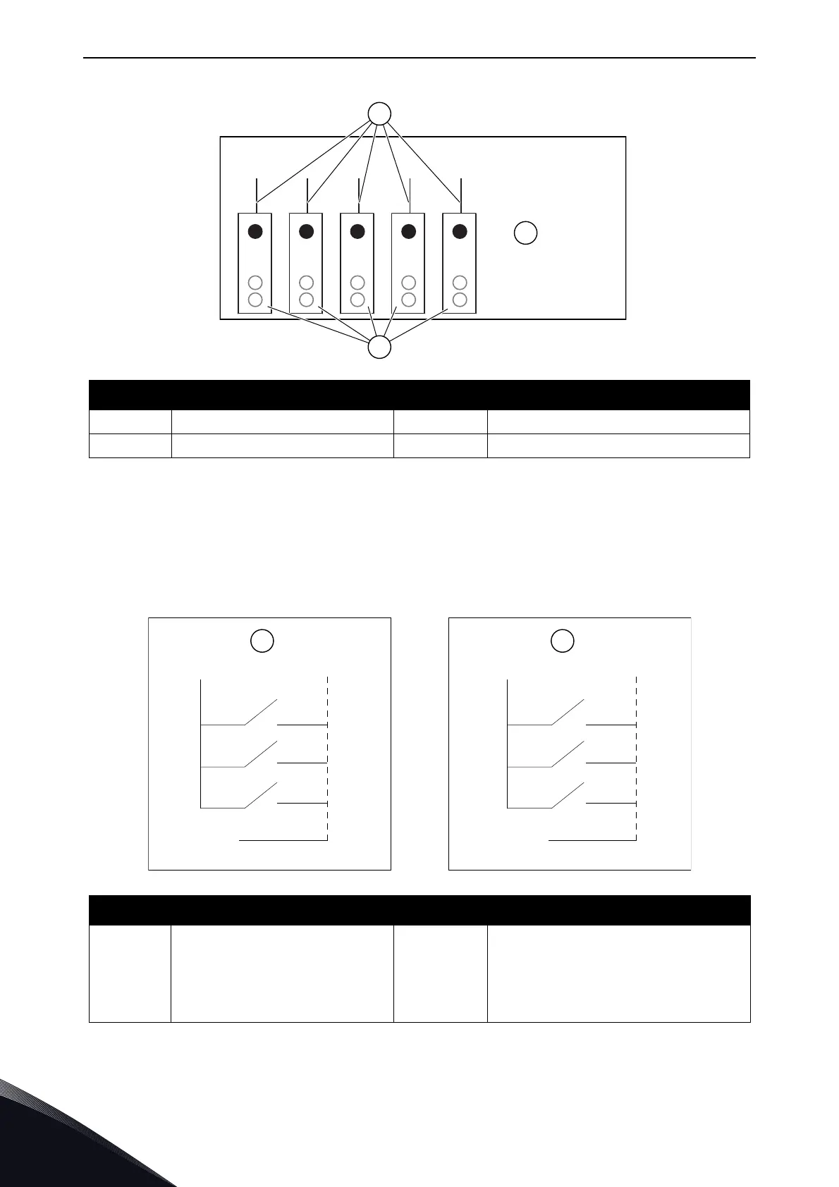
Figure 49. Maximum loads on +24V/EXT+24V output
Digital input signal inversions
The active signal level is different when the common inputs CMA and CMB (terminals 11 and 17) are
connected to +24 V or to ground (0 V). See Fig. 25. The 24 V control voltage and the ground for the
digital inputs and the common inputs (CMA, CMB) can be internal or external.
Figure 50. The Positive/Negative logic
# Reference # Reference
A Max. 150 mA C Max. 250 mA
B+24V out
# Reference # Reference
A
Positive logic (+24 V is the
active signal) = the input is
active when the switch is
closed.
B
Negative logic (0 V is the active sig-
nal) = the input is active when the
switch is closed. You must set the
jumper X3 to the position 'CMA/CMB
isolated from ground'.
=
A
B
C
A B
DIN1
+24 V
GND
DIN2
DIN3
CMA
+24 V
GND
DIN1
DIN2
DIN3
CMA

Table of Contents

Other manuals for Vacon NX series

Questions and Answers:

Question and Answer IconNeed help?

Do you have a question about the Vacon NX series and is the answer not in the manual?

Vacon NX series Specifications

General IconGeneral
Product typeAC Drive
Output voltage range0-Uin
Frequency range0-500 Hz
Enclosure classesIP00, IP21
Mounting typesWall
Braking chopperIntegrated or external
EMC filterBuilt-in or external
Control modesScalar, Vector
Protection featuresOvercurrent, overvoltage, undervoltage, overtemperature, short circuit
Communication optionsModbus, Profibus, CANopen, Ethernet
Ambient temperature range-10°C to +50°C
Cooling methodAir-cooled

Related product manuals