USER'S GUIDE____________________________________________________________________
6 ___________________________________________________________________ M210619EN-D
List of Figures
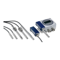
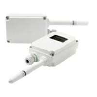
Figure 1 HMT310 Components ..............................................................18
Figure 2 HMT310 Probes .......................................................................19
Figure 3 Mounting with Mounting Plates.................................................22
Figure 4 Mounting Plate Dimensions......................................................23
Figure 5 Measurement Error at 100 %RH when Difference Between
Ambient and Sensor Temperature is 1 °C................................24
Figure 6 Horizontal Mounting of Probe...................................................24
Figure 7 Vertical Mounting of Probe .......................................................25
Figure 8 HMT314 Installation..................................................................26
Figure 9 Marking the Nut ........................................................................27
Figure 10 HMT318 Probe Dimensions (in mm)........................................29
Figure 11 Sealing of Fitting Body into Process.........................................30
Figure 12 Tightening the Clasp Nut..........................................................30
Figure 13 8-Pole Connector......................................................................32
Figure 14 Screw Terminal Connector.......................................................33
Figure 15 HyperTerminal Settings in Windows
®
2000 Environment ........37
Figure 16 Decrease of Sensor Gain Due to Interfering Chemical and
Effect of Chemical Purge Process............................................55
Figure 17 Location of Adjustment Button..................................................70
Figure 18 Accuracy over Temperature Range..........................................74
Figure 19 Transmitter Enclosure and Mounting Plate Dimensions ..........77
Figure 20 Probe Dimensions ....................................................................78
Figure 21 HMT313 Dimensions................................................................78
Figure 22 HMT314 Dimensions................................................................79
Figure 23 HMT315 Dimensions................................................................79
Figure 24 HMT317 Dimensions................................................................80
Figure 25 HMT318 Dimensions................................................................80
Figure 26 Duct Installation Kit...................................................................81
Figure 27 Swagelok Installation Kit for RH Probe ....................................82
Figure 28 Cable Installation with Cable Gland AGRO..............................83
Figure 29 Probe Installation with Cable Gland (not available from
Vaisala).....................................................................................84
Figure 30 Installing the HMT318 Probe Through a Ball Valve Assembly.85
 Loading...
