Appendix A ___________________ PROBE INSTALLATION KITS AND INSTALLATION EXAMPLES
VAISALA_______________________________________________________________________ 85
0507-043
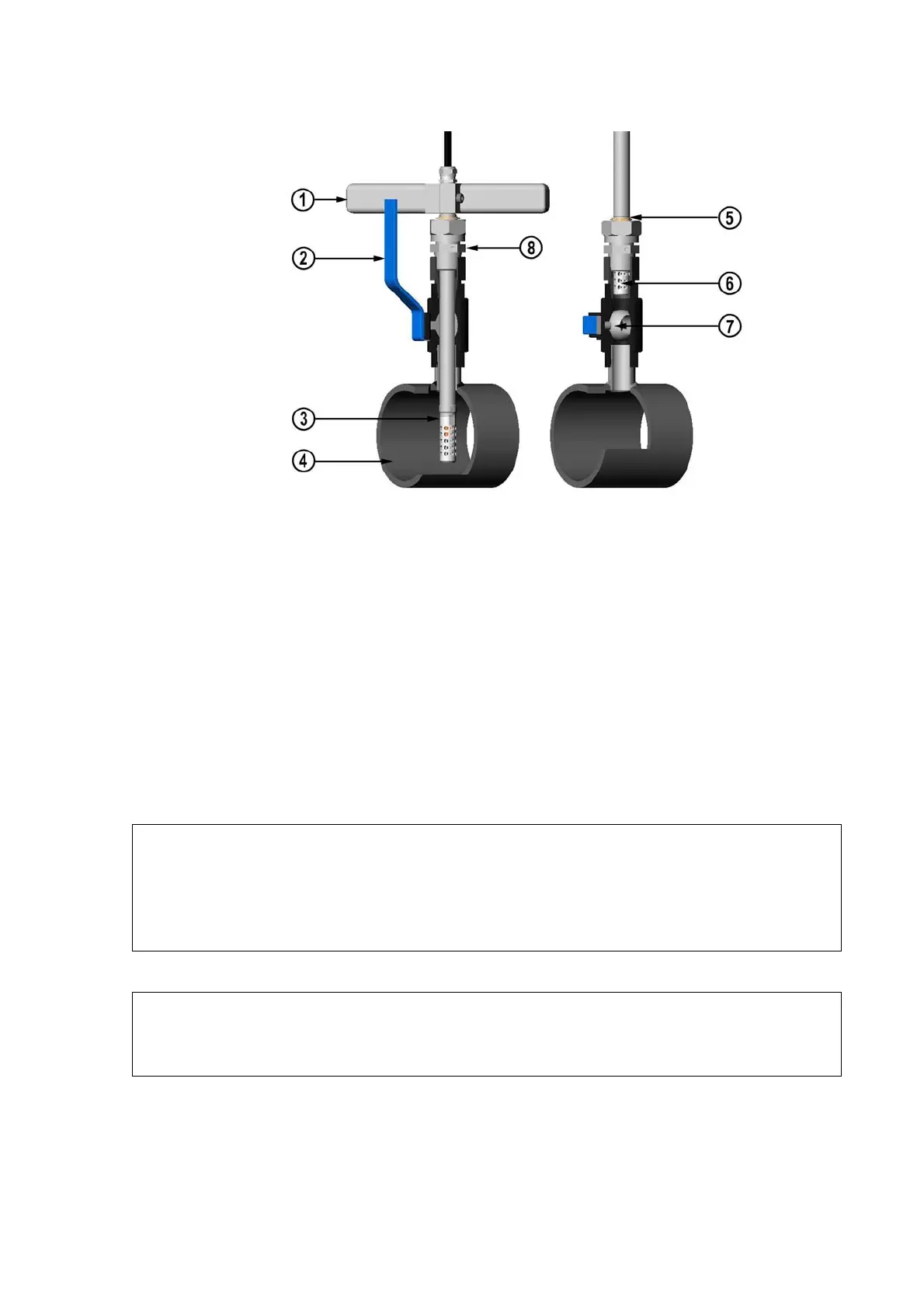
Figure 30 Installing the HMT318 Probe Through a Ball Valve
Assembly
The following numbers refer to Figure 30 above:
1 = Manual press tool
2 = Handle of the ball valve
3 = Probe
4 = Process chamber or pipeline
5 = Groove on the probe indicates the upper adjustment limit
6 = Filter
7 = Ball of the ball valve
8 = Clasp nut
NOTE
The probe can be installed in the process through the ball valve assembly
provided that the process pressure is less than 10 bars. This way, the
process does not have to be shut down when installing or removing the
probe. However, if the process is shut down before removing the probe,
the process pressure can be max. 20 bars.
NOTE
When measuring temperature dependent quantities make sure that the
temperature at the measurement point is equal to that of the process,
otherwise the moisture reading may be incorrect.