61
Installation Remote Battery and Wall Switch
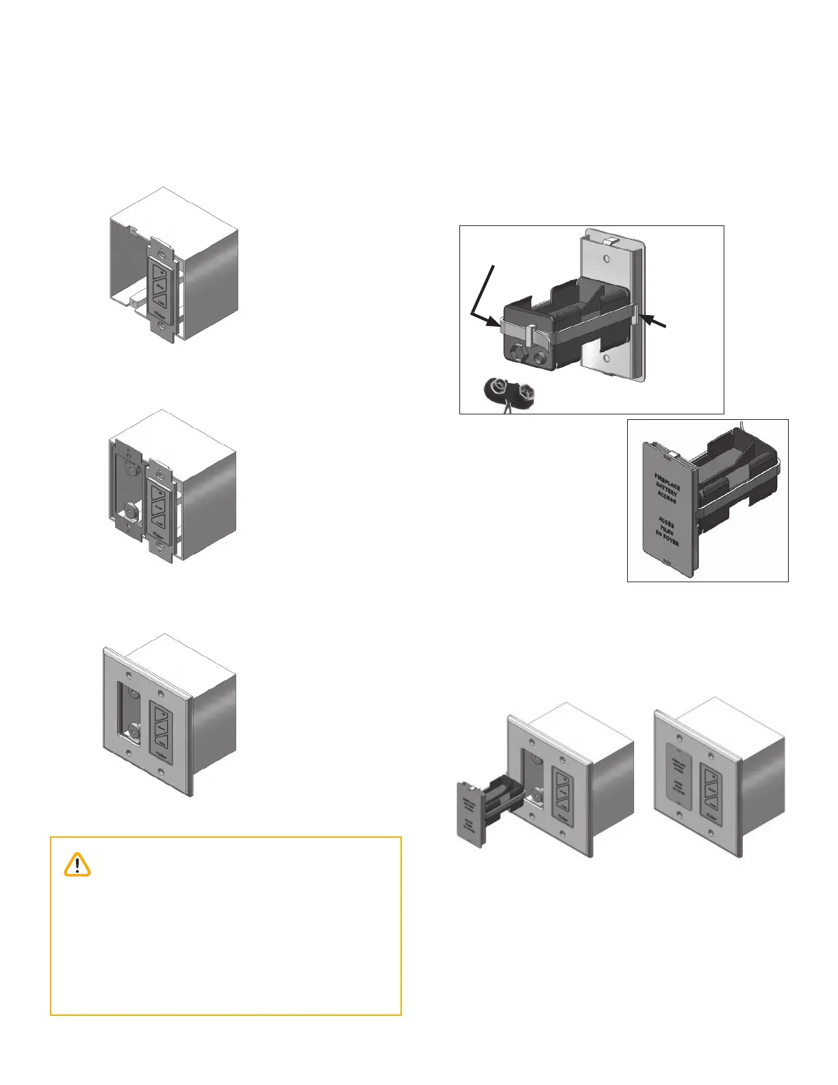
8. Mount switch plate to junction box with 2 long
screws provided. Note: switch position left or right
to suit homeowner wishes.
9. Locate and secure magnet plate using 2 ‘long’
screws provided
10. Place and secure cover plate to box using 4 screws
provided
11. Feed cable tie through the 2 side slots of battery
cover assembly.
12. Position battery holder to rear face and secure to-
gether with cable tie. note clearance is required for
battery snap connection.
13. Make the snap connection, load 4 AA alkaline bat-
teries into holder (included with fi replace) then feed
back into junction box assembly.
Note: Do not put batteries in the receiver, only in
the battery holder by the wall switch.
14. Test the operation of the wall switch—see Appendix
C - Wall Switch Operation on page 78.
Snap connector
Cable tie
Side slot
Rear view
Front view
Caution
DO NOT USE a screwdriver or other metallic
object to remove the batteries from the battery
holder or the handset! This could cause a short
circuit to the receiver.
To avoid short-circuit to the receiver, position the
antenna so that it DOES NOT TOUCH the ignition
wire.