48
X
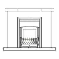
Connect Gas Supply
The gas supply inlet connection is a
3/8” NPT male connector located on
the right hand side of the fi rebox.
The unit is supplied with a stainless steel fl ex line to
allow the appliance to be disconnected for service. An
individual shut-off valve (not supplied) is required on
the supply line ahead of the fl ex connector.
Use only new black iron or steel pipes, CSST, or copper
tubing if acceptable—check local codes. Note that in
USA, copper tubing must be internally tinned for pro-
tection against sulfur compounds.
Unions in gas lines should be of ground joint type.
The gas supply line must be sized and installed to pro-
vide a supply of gas suffi cient to meet the maximum de-
mand of the appliance without undue loss of pressure.
Sealant used must be resistant to the action of all gas
constituents including LP gas. Sealant should be applied
lightly to male threads to ensure excess sealant does
not enter gas lines.
1-5/8”
[40 mm]
6-1/8”
[156 mm]
Gas line
access hole
1-3/8” [35 mm]
diam.
Gas line access—right side view
Pressure test the supply line for leaks
The appliance and its individual shut-off valve must be
disconnected from the gas supply piping system during
any pressure testing of that system at test pressures in
excess of 1/2 psig (3.5 kPa).
The appliance must be isolated from the gas supply
piping system by closing its individual manual shut-off
valve during any pressure testing of the gas supply pip-
ing system at test pressures equal to or less than 1/2
psig (3.5 kPa).
Failure to either disconnect or isolate the appliance
during pressure testing may result in regulator or valve
damages and void the warranty. Consult your dealer in
case of damages.
Pressure Test Points
The minimum supply pressure is given in this manual—
see Specifi cations on page 6.
All piping and connections must be tested for leaks af-
ter installation or servicing. All leaks must be corrected
immediately.
When testing for leaks:
• Make sure that the appliance is turned off .
• Open the manual shut-off valve.
• Test for leaks by applying a liquid detergent or soap
solution to all joints. Bubbles forming indicate a gas leak.
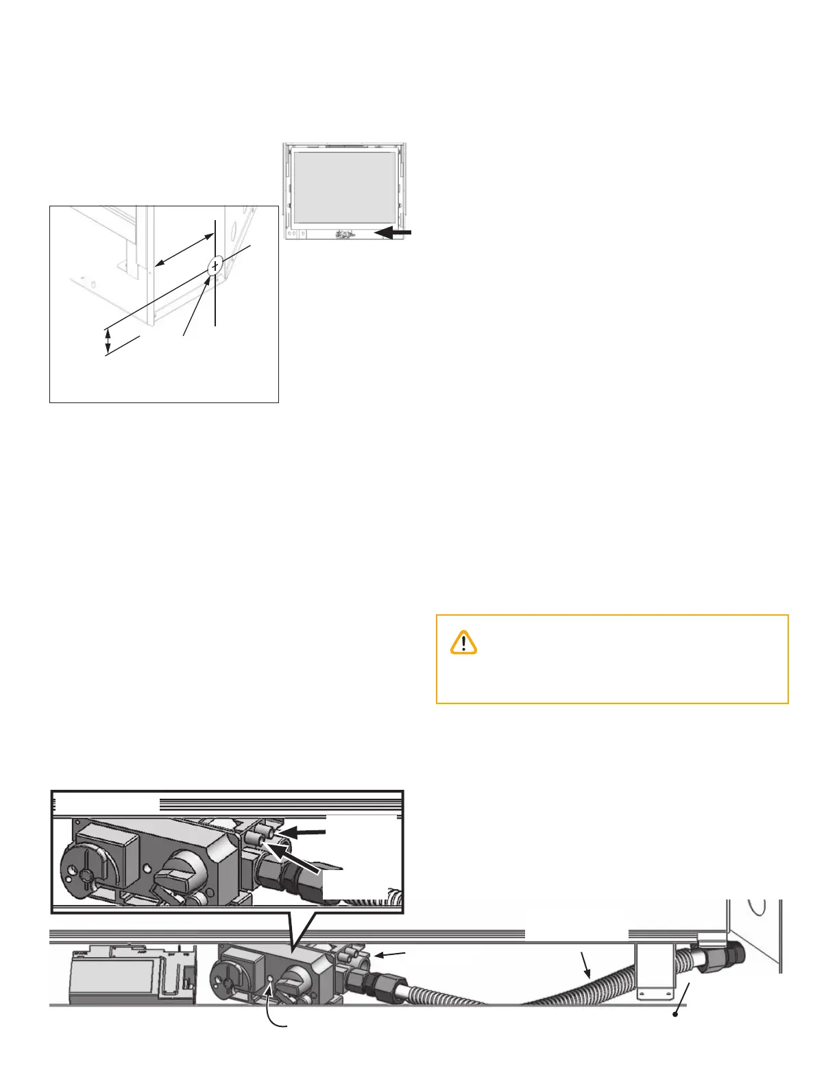
The pressure test tapping locations are shown in the
fi gure below. An internal regulator within the valve
controls the burner manifold pressure.
The correct pressure range is shown in Specifi cations on
page 6 of this manual. The pressure check should
be made with the burner alight and at its highest set-
ting. See Appendix A - Lighting Instructions Plate on page
70 in this manual for full operating details.
Caution
Never use an open flame to check for leaks!
Correct any leak detected immediately.
Gas Supply
Installation
Valve assembly
Pressure testing
Manifold pressure adjustment
behind plastic cap
Control Valve
Valve inlet
pressure
Manifold
test
pressure
Receiver
Flexible connector
supplied with unit
Valve cover on
front of the
appliance