VAMP 257 Feeder and motor manager
Technical description
VAMP Ltd
60
VAMP 24h support phone : +358 (0)20 753 3264
VM257.EN002
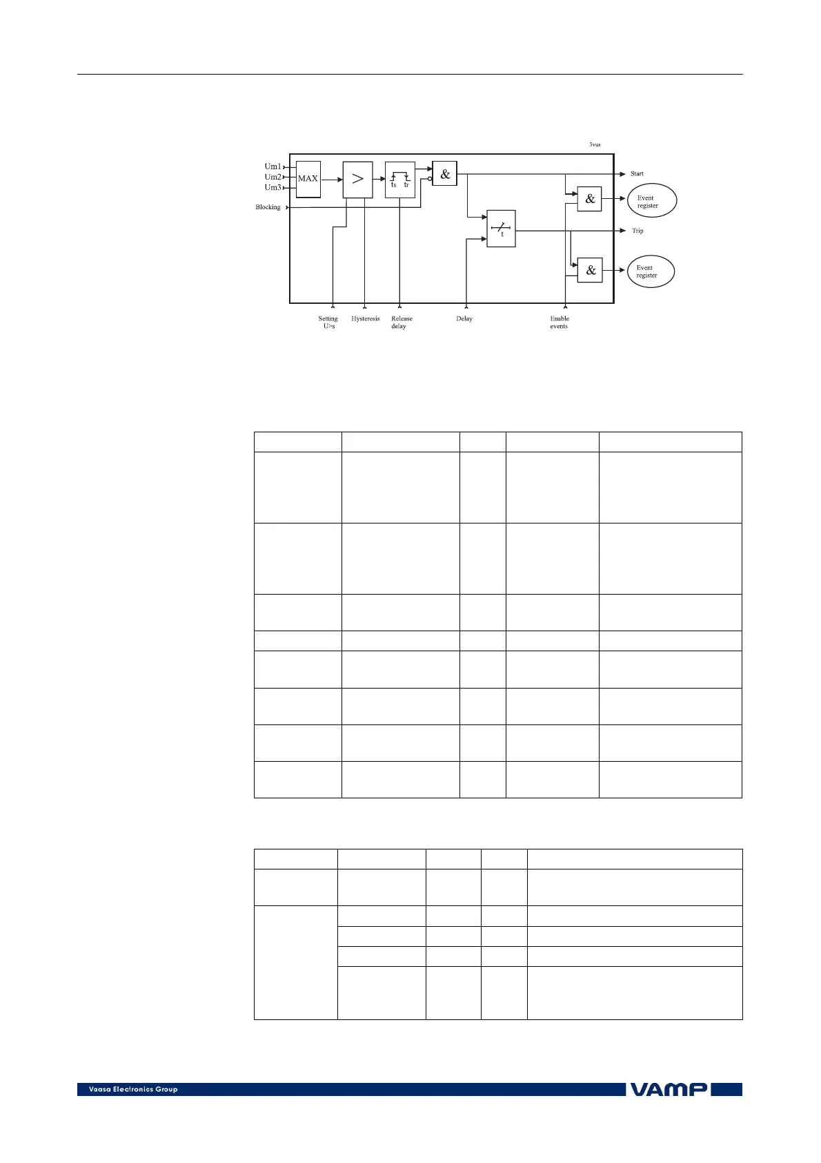
Figure 2.3.17-3 shows the functional block diagram of the
overvoltage function stages U>, U>> and U>>>.
Figure 2.3.17-3. Block diagram of the three-phase overvoltage stages U>,
U>> and U>>>
Setting parameters of overvoltage stages:
U>, U>>, U>>> (59)
Parameter Value Unit Default Description
U>, U>>,
U>>>
50 … 150 (U>,
U>>)
50 … 160
(U>>>)
%Un 120 (U>)
130
(U>>, U>>>)
Overvoltage setting
t>, t>>,
t>>>
0.08 … 300.0
(U>,U>>)
0.06 … 300.00
(U>>>)
s 0.20 (U>)
0.10
(U>>, U>>>)
Definite operation
time
ReleaseDly 0.06 … 300.0 s -
Release delay [s]
(only U>)
Hysteresis 0.1 … 20.0 % - Deadband (only U>)
S_On
Enabled;
Disabled
- Enabled Start on event
S_Off
Enabled;
Disabled
- Enabled Start off event
T_On
Enabled;
Disabled
- Enabled Trip on event
T_Off
Enabled;
Disabled
- Enabled Trip off event
Measured and recorded values of overvoltage stages:
U>, U>>, U>>> (59)
Parameter Value Unit Description
Measured
value
Umax V Maximum value of line voltages
SCntr - Start counter (Start) reading
TCntr - Trip counter (Trip) reading
Flt %U
n
The max. fault value
Recorded
values
EDly %
Elapsed time as compared to
the set operating time; 100% =
tripping