VAMP Ltd Feeder and motor manager
Technical description
VAMP 257
VM257.EN002 VAMP 24h support phone : +358 (0)20 753 3264
49
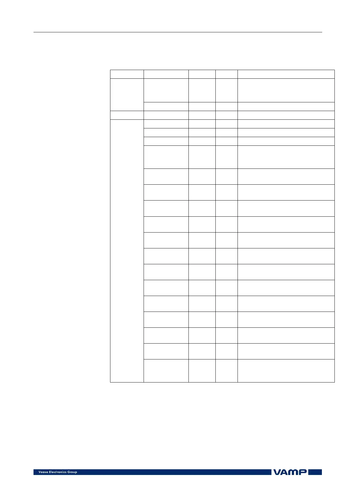
Measured and recorded values of capacitor bank
unbalance protection:
I
02
>, I
02
>> (50N/51N)
Parameter Value Unit Description
Io2, Io2 Pu unbalance current Io2
(including the natural unbalance
current)
Measured
values
dIo A Compensated unbalance current
Display Io2>, Io2>> A Setting value Io2
SCntr - Cumulative start counter
TCntr - Cumulative trip counter
Flt pu The max. fault value
EDly %
Elapsed time as compared to the
set operating time; 100% =
tripping
Isaved A
Recorded natural unbalance
current
SavedA deg
Recorded phase angle of natural
unbalance current
Faults (Io2>>
only)
-
Allowed number of element
failures
Total (Io2>>
only)
-
Actual number of element
failures in the bank
Clear (Io2>>
only)
-, Clear - Clear the element counters
L1-B1 (Io2>>
only)
-
Number of element failures in
phase L1 in brach 1 (left side)
L1-B2 (Io2>>
only)
-
Number of element failures in
phase L1 in brach 2 (right side)
L2-B1 (Io2>>
only)
-
Number of element failures in
phase L2 in brach 1 (left side)
L2-B2 (Io2>>
only)
-
Number of element failures in
phase L2 in brach 2 (right side)
L3-B1 (Io2>>
only)
-
Number of element failures in
phase L3 in brach 1 (left side)
L3-B2 (Io2>>
only)
-
Number of element failures in
phase L3 in brach 2 (right side)
Locat (Io2>>
only)
-
Changed unbalance current
(after automatic compensation)
Recorded
values
LocAng
(Io2>> only)
-
Changed phase angle of the
unbalance current (after
automatic compensation)
2.3.14. Residual voltage protection (59N)
The residual voltage function comprises two separately adjust-
table residual voltage stages (stage U
0
> and U
0
>>).
The residual voltage function measures the fundamental
frequency component of the residual voltage. This means that
harmonics will not cause a trip. The protection stages operate
with definite time characteristics.