VAMP 257 Feeder and motor manager
Technical description
VAMP Ltd
50
VAMP 24h support phone : +358 (0)20 753 3264
VM257.EN002
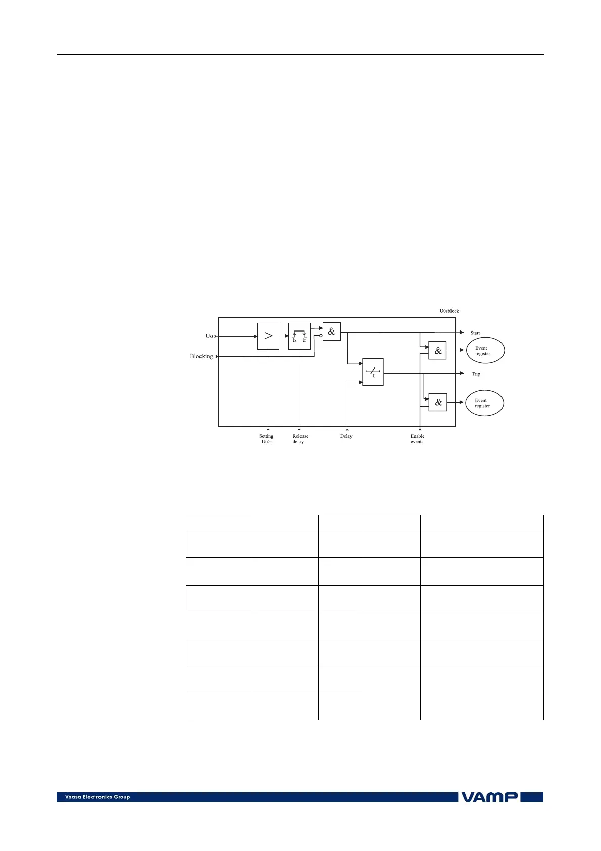
The function starts if the actual value for the residual voltage
exceeds the setting value. If the overvoltage situation continues
after the start delay has elapsed, the function trips.
The residual voltage is either measured with voltage
transformers (e.g. broken delta connection) or calculated from
the phase voltages according to the selected protection mode:
• Phase: the residual voltage is calculated from the phase
voltages and therefore a separate residual voltage
transformer is not needed. The setting values are relative to
the VT secondary voltage (U
sec
) defined in the configuration.
• 2 Line+U
0
/ 2 side+U
0
: the residual voltage is measured
with voltage transformers (e.g. a broken delta connection).
The setting values are relative to the VT
0
secondary voltage
(U
0sec
) defined in the configuration.
• 3 side: the residual voltage not available
Figure 2.3.14-1. Block diagram of the residual voltage stages U
0
> and U
0
>>
Setting parameters of residual voltage protection stages:
U
0
>, U
0
>>, (59N)
Parameter Value Unit Default Description
Uo>, Uo>> 1.0 … 60 % Uon 10 (Uo>)
20 (Uo>>)
Setting value
t>, t>> 0.3 … 300.0 s 2.0 (t>)
0.5 (t>>)
Definite operation time
ReleaseDly s
Release delay [s] (only
Uo>)
S_On
Enabled;
Disabled
- Enabled Start on event
S_Off
Enabled;
Disabled
- Enabled Start off event
T_On
Enabled;
Disabled
- Enabled Trip on event
T_Off
Enabled;
Disabled
- Enabled Trip off event