VAMP 257 Feeder and motor manager
Technical description
VAMP Ltd
122
VAMP 24h support phone : +358 (0)20 753 3264
VM257.EN002
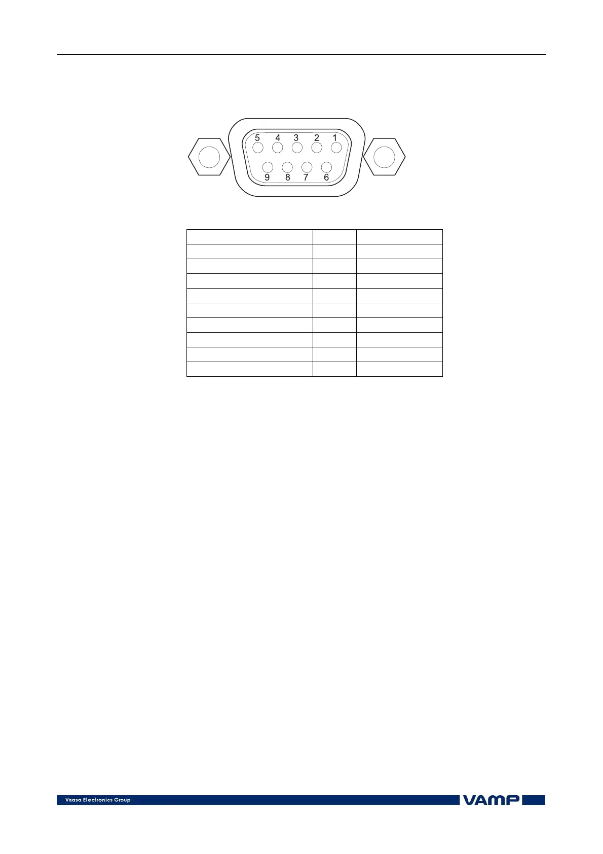
4.6.2. Pin assignment of the front communication
port
Figure 4.6.2-1. Pin numbering of the front communication port
Port (LOCAL) Pin Signal
Front 1
Front 2 RX /RS-232 in
Front 3 TX /RS-232 out
Front 4 DTR / +8Vout
Front 5 GND
Front 6 DSR / in
Front 7
Front 8
Front 9
NOTE! DSR must be connected to DTR to activate the front panel
interface.
4.6.3. Protocols
SPA-Bus
The manager has full support for the SPA-Bus protocol
including the following features:
• event transfer
• time synchronization
• the transfer of status data
• the transfer of measurement data
• the reception of control commands
• the reading and writing of setting values
• the reading of multiple consecutive status data bits,
measurement values or setting values with one
message.
The physical connection from a manager is by default 9-pin D-
connector with TTL level signals. This can only be used to
connect to an external bus connection device or to a modem.
Alternatively, RS-232 can be selected with a dip switch.
The manager can be equipped with a fibre optic option module,
which includes fibre optic connectors (two plastic/two glass/one
plastic and one glass).