VAMP 257 Feeder and motor manager
Technical description
VAMP Ltd
116
VAMP 24h support phone : +358 (0)20 753 3264
VM257.EN002
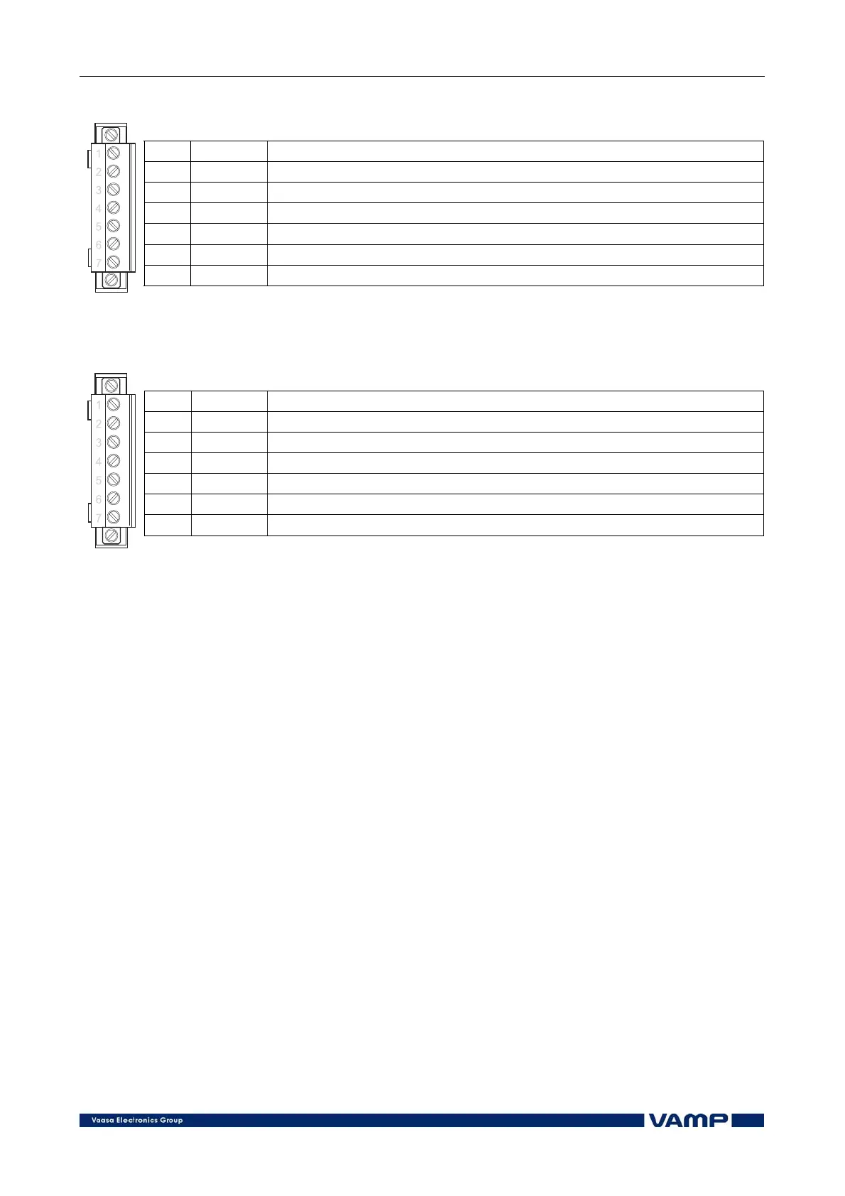
Terminal X6
No: Symbol Description
1 BI External arc light input
2 BO Arc light output
3 COM Common connector of arc light I/O
4 S1>+ Arc sensor 1, positive connector *
5
S1>−
Arc sensor 1, negative connector *
6 S2>+ Arc sensor 2, positive connector *
7
S2>−
Arc sensor 2, negative connector *
*) Arc sensor itself is polarity free
Terminal X6 with DI19/DI20 option
No: Symbol Description
1 DI19 Digital input 19
2 DI19 Digital input 19
3 DI20 Digital input 20
4 DI20 Digital input 20
5 -- --
6 S1>+ Arc sensor 1, positive connector *
7
S1>−
Arc sensor 1, negative connector *
*) Arc sensor itself is polarity free
4.2. Analogue measurements
• Phase currents I
L1
, I
L2
and I
L3
(terminals X1: 1-6)
• Earth fault current I
0
(terminals X1: 7-8)
• Earth fault current I
02
(terminals X1: 9-10)
• Voltage measurement modes:
• Phase: voltages U
L1
, U
L2
and U
L3
(terminals X1: 11-14
and 17-18)
• 2 Line+U
0
: Line voltages U
12
and U
23
(terminals X1:
11-14) and neutral voltage U
0
(terminals X1:17-18)
4.3. Digital inputs
Further, the manager can collect status information and alarm
signals via 32 digital inputs (terminals X3: 2-7, X7: 1-14 and
X8: 1-20). The digital inputs can also be used to block
protection stages under certain conditions. The six digital
inputs in manager X3 use an internal 48 V dc auxiliary voltage
of the manager (terminal X3: 1).
Potential-free contacts must be available in the protected object
for transferring status information to the manager. In VAMP
257 the digital inputs 7-18 in terminal X7 and the digital
inputs 21-32 in terminal X8 need an external control voltage.