VAMP Ltd Feeder and motor manager
Operation and configuration
VAMP 257
VM257.EN002 VAMP 24h support phone +358 (0)20 753 3264
15
3.1.2. Basic menu structure of protection functions
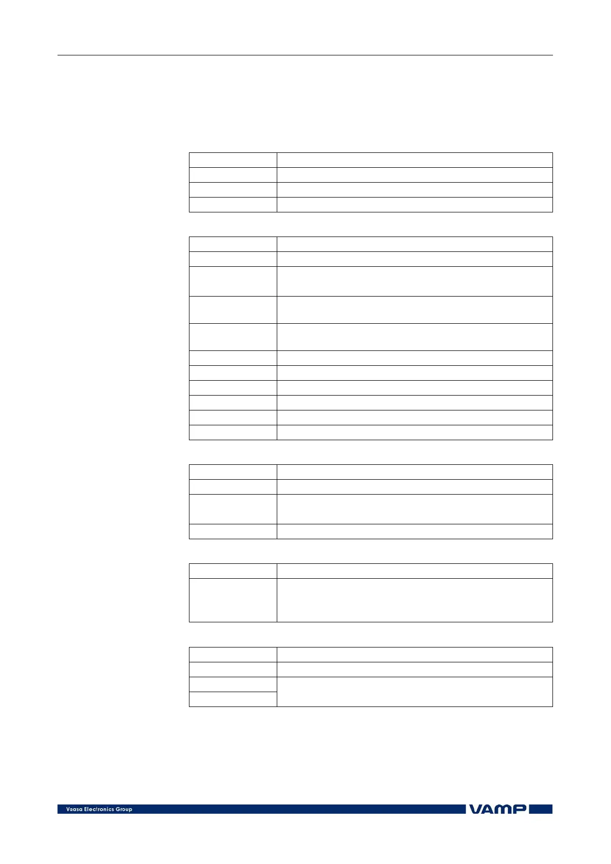
Example I>:
I>STATUS:
Status Trip State of protection function (-, Start, Trip)
SCntr 8 Start counter
TCntr 7 Trip counter
Force Off Forced operation of state (ON, OFF)
SET I> (several SET menus possible):
ILmax 100A Actual value, the value on which the protection is based
Status - State of protection function (-, Start, Trip)
I> 110A Set value of protection function [A]
I> 1.10xI
n
Set value of protection function [pu]
Curve IEC
Delay curve family ( IEC, IEEE, IEEE2, RI, Prg1-Prg3,
DT)
Type DT
Selection of delay time curve (DT, NI, VI, EI, LTI,
Parameters)
k> 0.50 Inverse time coefficient
t> 0.30s Operation delay
Dly20x 1.13s Inverse delay (20x)
Dly4x 2.48s Inverse delay (4x)
Dly2x 5.01s Inverse delay (2x)
Dly1x 35.90s Inverse delay (1x)
LOG I>:
Index 1 Order number of start 1 - 8
Type - Recorded event data
Flt A Maximum fault current [A]
Load A 1 s mean value of the pre-fault phase current [A]
EDly % Duration of fault (100% = the stage has tripped)
LOG2 I>:
Index 1 Order number of start 1 - 8
2002-08-22 Event time stamp
20:34:11
67ms
I> event mask:
St_On Selection of events into Event list (Enabled)
St_Off Selection of events into Event list (Enabled)
Tr_On Selection of events into Event list (Enabled)
Tr_Off Selection of events into Event list (Enabled)