VAMP 257 Feeder and motor manager
Technical description
VAMP Ltd
118
VAMP 24h support phone : +358 (0)20 753 3264
VM257.EN002
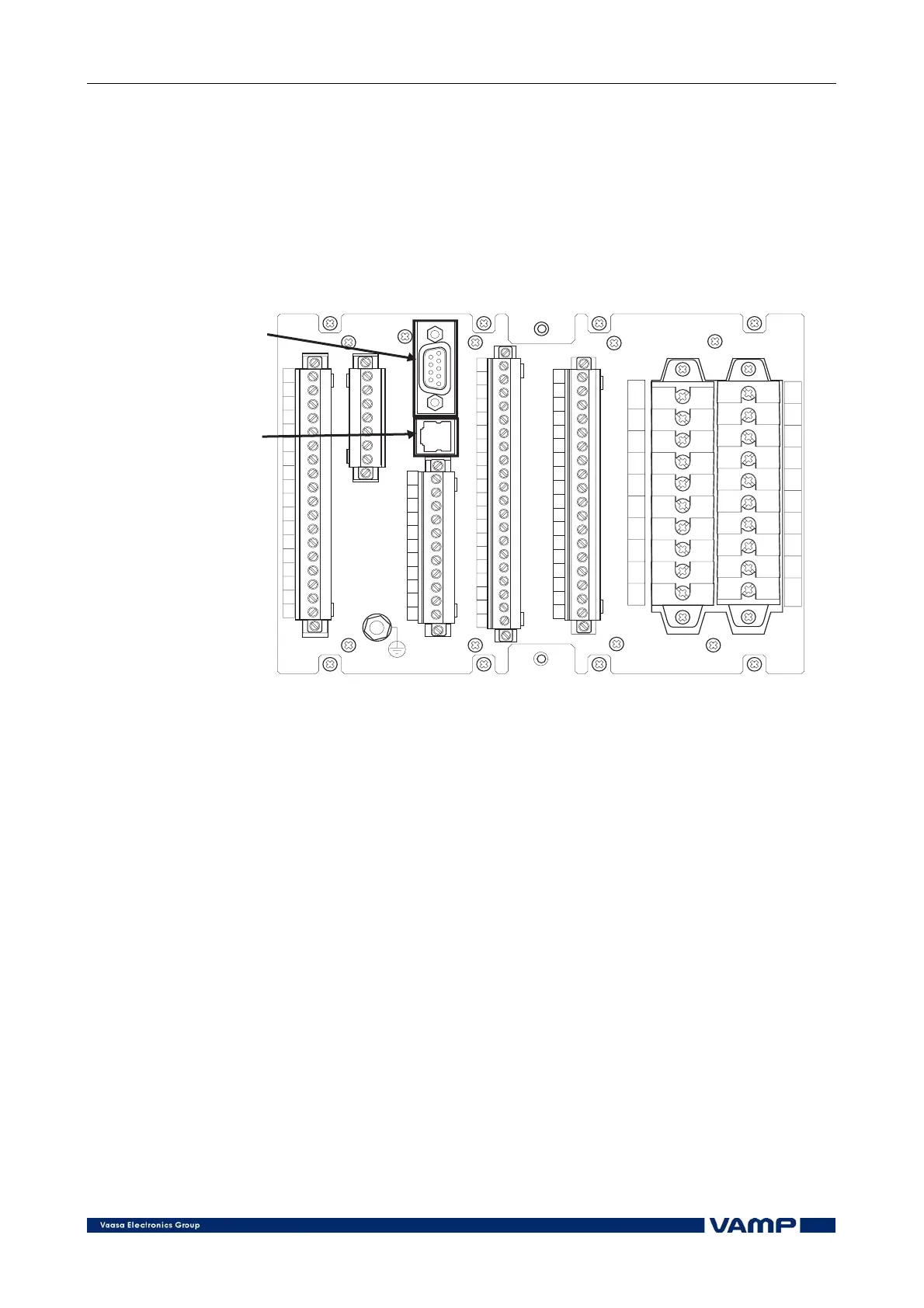
4.6. Serial communication connection
VAMP 257 can be equipped with two optional communication
modules: Communication Module 1 and Communication
Module 2. The physical location of the modules is at the back of
the relay. The modules can be installed in the field (when
power is first turned off).
1
2
3
4
5
6
7
8
9
10
11
12
13
14
15
16
17
18
X3
X1
VYX060A
1
3
5
7
9
11
13
15
17
19
2
4
6
8
10
12
14
16
18
20
X6
X2
1
2
3
4
5
6
7
1
2
3
4
5
6
7
8
9
10
11
12
13
14
15
16
17
18
X7
VAMP257serialcommunication
1
2
3
4
5
6
7
8
9
10
11
1
2
3
4
5
6
7
8
9
10
11
12
13
14
15
16
17
18
19
20
X8
Communication
module1.
Communication
module2.
Figure 4.6-1 VAMP257 back panel serial communication connection
The internal connection in both communication modules is
identical (see Figure 4.6-2). The transmit and receive lines of
all the three “logical communication ports” REMOTE, LOCAL
and EXTENSION port are available for both modules (RS-232
signal levels). Depending on the module type one or more of
these ports are physically available at the external connector.
The communication modules convert the RS-232 signal levels to
some other levels e.g. TTL, RS-485 or fibre-optics. The modules
may also contain intelligence to make protocol conversion on
software level.