VAMP Ltd Feeder and motor manager
Technical description
VAMP 257
VM257.EN002 VAMP 24h support phone : +358 (0)20 753 3264
119
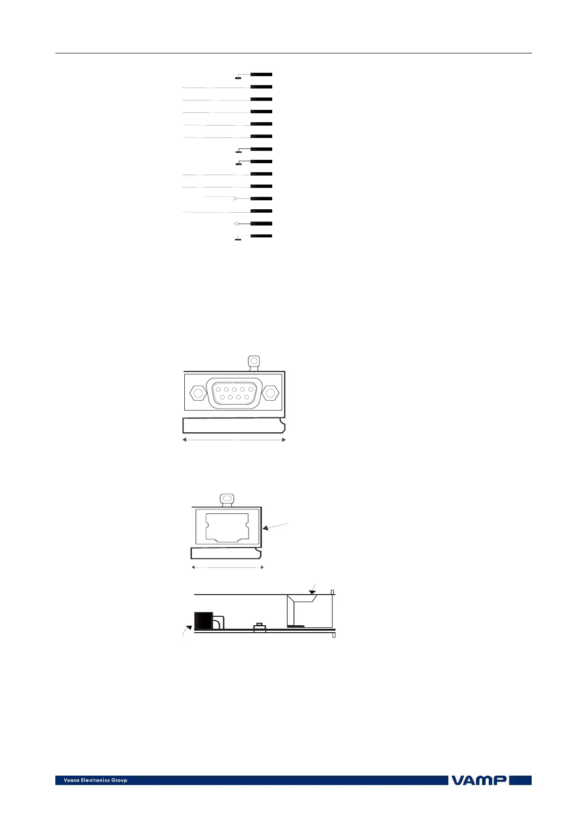
EXT TX
EXT RX
REMDTE TX
REMDTE RX
+8Vdc
LOCAL TX
LOCAL RX
UART_OUT
Sync.in
OPTx_ID
X3-1
X3-2
X3-3
X3-4
X3-5
X3-6
X3-7
X3-8
X3-9
X3-10
X3-11
X3-13
X3-12
X3-14
Internal connection
Figure 4.6-2 Internal connection to communication modules
The internal connection of the communication modules contain
the RX/TX signals from the communication ports, general
output (UART_OUT), clock sync/general input (Sync.in) and
OPTx_ID for module detection.
31 mm
31mm
Figure 4.6-3 Communication module with a height of 31mm
18 mm
Internal 14-pin connector, RS-
232 signal levels for REMOTE,
LOCAL and EXTENSION ports
External connector
External connector, signal levels
depend on the type of the
module
18mm
Figure 4.6-4 Communication module with a height of 18mm
The device has a 31mm high “slot” for Communication Module
1 and 18mm high “slot” for Communication Module 2. The
option modules are either 31mm or 18mm high, the 18mm
modules can be used either in the 31mm or 18mm slot.