VAMP 257 Feeder and motor manager
Technical description
VAMP Ltd
74
VAMP 24h support phone : +358 (0)20 753 3264
VM257.EN002
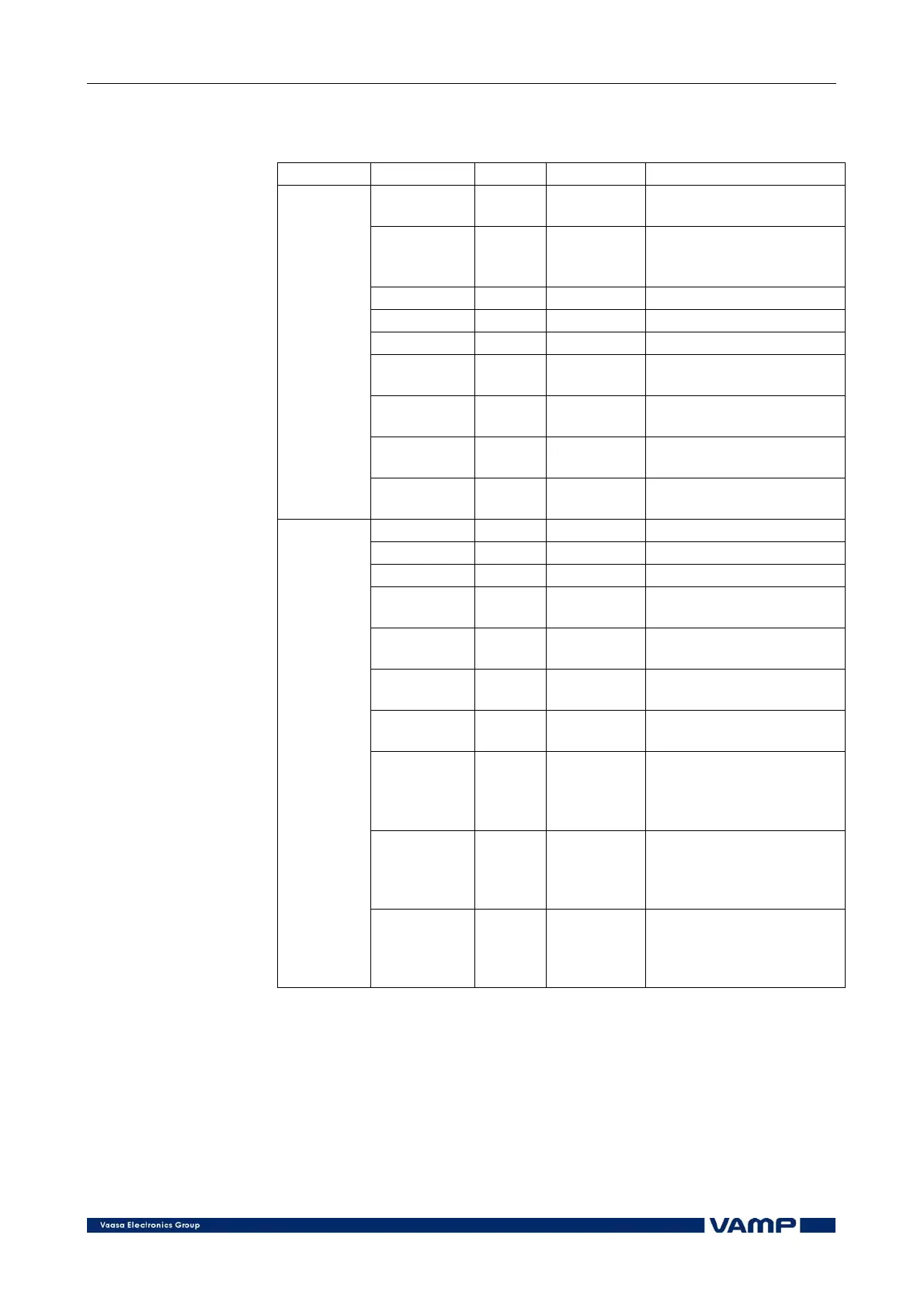
Measured and recorded values of synchrocheck stages:
SyC1, SyC2 (25)
Parameter Values Unit Description
df - Hz
Measured frequency
difference
dU - % Un / deg
Measured voltage
amplitude and phase
angle difference
UState - - Voltage status (e.g. DD)
SState - - Synchrocheck status
ReqTime - - Request time status
f
1)
- Hz
Measured frequency
(reference side)
fy
1)
- Hz
Measured frequency
(comparison side)
U12
1)
- % Un
Measured voltage
(reference side)
Measured
values
U12y
1)
- % Un
Measured voltage
(comparison side)
ReqCntr - - Request counter
SyncCntr - - Synchronising counter
FailCntr - - Fail counter
f
1)
- Hz
Recorded frequency
(reference side)
fy
1)
- Hz
Recorded frequency
(comparison side)
U12
1)
- % Un
Recorded voltage
(reference side)
U12y
1)
- % Un
Recorded voltage
(comparison side)
dAng - Deg
Recorded phase angle
difference, when close
command is given from
the function
dAngC - Deg
Recorded phase angle
difference, when the
circuit-breaker actually
closes.
Recorded
values
EDly - %
The elapsed time
compared to the set
request timeout setting,
100% = timeout
1)
Please note that the labels (parameter names) change according to the
voltage selection.
The following signals of the both stages are available in the
output matrix and the logic: “Request”, “OK” and “Fail”. The
“request”-signal is active, when a request has received but the
breaker is not yet closed. The “OK”-signal is active, when the
synchronising conditions are met, or the voltage check criterion
is met. The “fail”-signal is activated, if the function fails to close