VAMP Ltd Feeder and motor manager
Technical description
VAMP 257
VM257.EN002 VAMP 24h support phone : +358 (0)20 753 3264
81
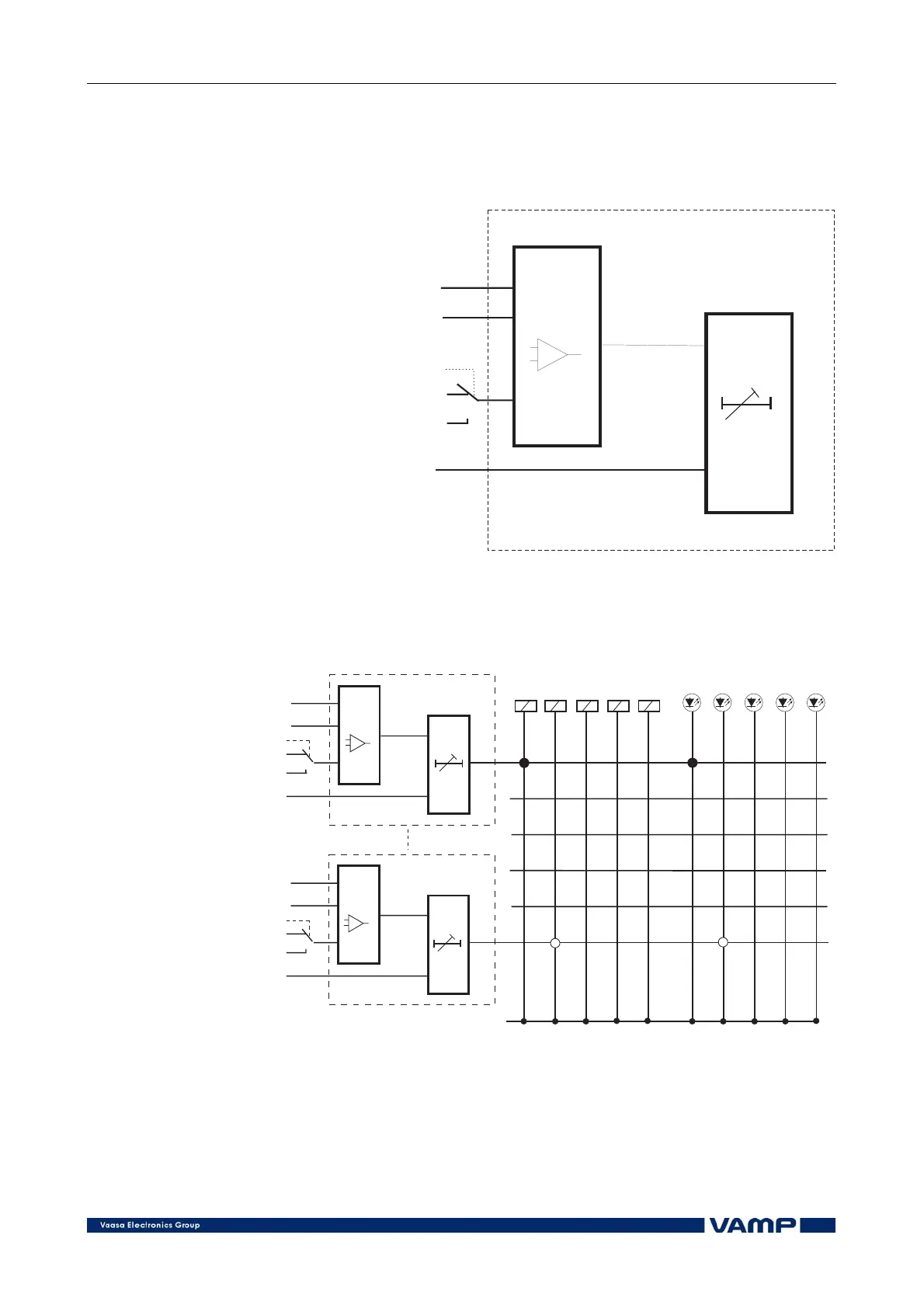
The outputs of the programmable stages can control any
combination of output relays and indicator LEDs, see Figure
2.3.27-1 and Figure 2.3.27-2
In
Ref
Mode
Start
Delay
I, U, P, Q, S, f, THDcos
Set limit value
Set delay 0.08 - 300s
basicalarmstage
Mode Select
>
<
Figure 2.3.27-1 Principle of programmable stage
alarmstages
1
2
3
4
5
6
T1 T2 A1 A2 A3 A B C D E
Start
Delay
Ref
Mode
In
RESET
Latches
In
Ref
Mode
Start
Delay
Figure 2.3.27-2 Programmable stages in the output matrix
Start and trip signals can also be activated using the Force-
setting of each programmable stage.