VAMP Ltd Feeder and motor manager
Technical description
VAMP 257
VM257.EN002 VAMP 24h support phone : +358 (0)20 753 3264
85
After each period, the number of interruptions and the total
interruption time are stored as previous values. The
interruption counter and the total time are cleared for a new
period. The pre-previous values are overwritten.
The voltage interruption is based on the value of the positive
sequence voltage U
1
and a user given limit value U
1
<.
Whenever the measured U
1
goes below the limit, the
interruption counter is increased, and the total time starts
cumulating.
Shortest recognized interruption time is 40 ms. If the voltage-
off time is shorter it may be recognized depending on the depth
of the voltage dip, the ratio of the limit and the voltage value
before the dip.
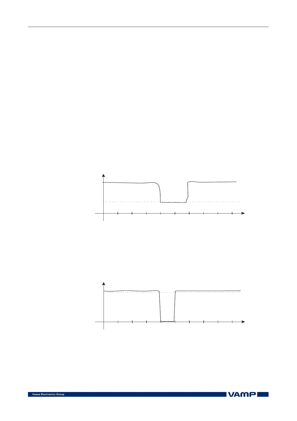
If the voltage has been significantly over the limit U
1
< and then
there is a small and short underswing, it will not be recognized
(Figure 2.4.4-1).
Time
(ms)
Voltage U
1
U <
1
10 20 30 40 50 607080 90
VoltageSag1
Figure 2.4.4-1. Short voltage sag which is probably not recognized
On the other hand, if the limit U
1
< is high and the voltage has
been near this limit, and then there is a short but very deep
dip, it will be recognized (Figure 2.4.4-2).
Time
(ms)
Voltage U
1
U <
1
10 20 30 40 50 607080 90
VoltageSag2
Figure 2.4.4-2. Short voltage sag that is recognized