VAMP Ltd Feeder and motor manager
Technical description
VAMP 257
VM257.EN002 VAMP 24h support phone : +358 (0)20 753 3264
107
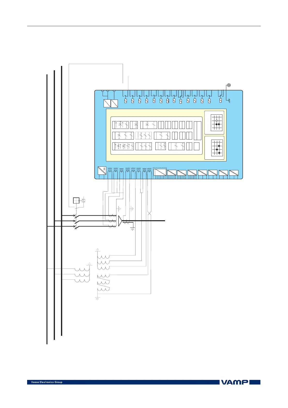
If there is a fault in one of the lines, only the faulty line will be
switched off because of the direction functions of the relays R3
and R4. A detailed schematic of e.g. the relay R3 is shown in
Figure 3.3-2.
-
+
application1_vamp257
IL1
IL2
IL3
I
01
I
01
Uo
I
02
I
02
U12
U23
~
Blocking and
output matrix
Autorecloser
matrix
VAMP 257
Remote
Local
Front
T1
T2
T3
T4
A1
IF
X1:1
X1:2
X1:3
X1:4
X1:5
X1:6
X1:7
X1:8
X1:9
X1:12
X1:13
X1:14
X1:17
X1:18
X1:10
X1:11
X3:17
X3:18
X3:14X3:14
X3:15
X3:12
X3:13
X7:17
X7:18
X7:15
X7:16
X2:9
X2:10
X2:11
X3:1 +48V
X3:2 DI1
X3:3 DI2
X3:4 DI3
X3:5 DI4
X3:6 DI5
X3:7 DI6
Protection functions
X6:1
X6:2
X6:3
X6:4
X6:5
X6:6
X6:7
O
p
tion
Block
CBFP
50BF
If2 >
68
3I<
37
3I>
3I>>
3I>>>
50 / 51
3I>
3I>>
3I>>>
3I>>>>
67
I >,I
>
002
I >>
,I
>>
002
50N/51N
I/I
>
21
46
U>
0
U>
0
59N
U<
U<<
U<<<
27
U>
U>>
U>>>
59
f ><
f >><<
810/81U
f<<
f<
81U
I >
0
I >>
0
67N
ArcI
>
50AR
T>
49
I2>>
47
I2>
46
Ist>
48
N>
66
Auto Reclose
7979
25
DI
DI
DI
DI
DI
DI
DI
X7:1 DI7
X7:2 DI8
X7:3 DI9
X7:4 DI10
X7:5 DI11
X7:6 DI12
X7:7 comm
X8:1 DI21
x9/ Remote
/EXT.Io
x 10/ Remote
/EXT.Io
T5
A2
A3
A4
A5
X8:19
X8:20
X8:17
X8:18
X8:15
X8:16
X8:13
X8:14
X3:9
X3:10
X3:11
T6
T7
T8
X2:7
X2:8
X2:5
X2:6
X2:3
X2:4
X2:1
X2:2
X8:2 DI22
X8:3 comm
X8:4 DI23
X8:5 DI24
X8:6 comm
X8:7 DI25
X8:8 DI26
X8:9 comm
X8:10 DI27
X8:11 DI28
X8:12 comm
X7:8 DI13
X7:9 DI14
X7:10 DI15
X7:11 DI16
X7:12 DI17
X7:13 DI18
X7:14 comm
Figure 3.3-2. Example connection VAMP 257. Both short-circuits and earth-
faults will be detected. The outgoing line is one of several parallel lines or
the line is feeding a ring network.