VAMP Ltd Feeder and motor manager
Technical description
VAMP 257
VM257.EN002 VAMP 24h support phone : +358 (0)20 753 3264
113
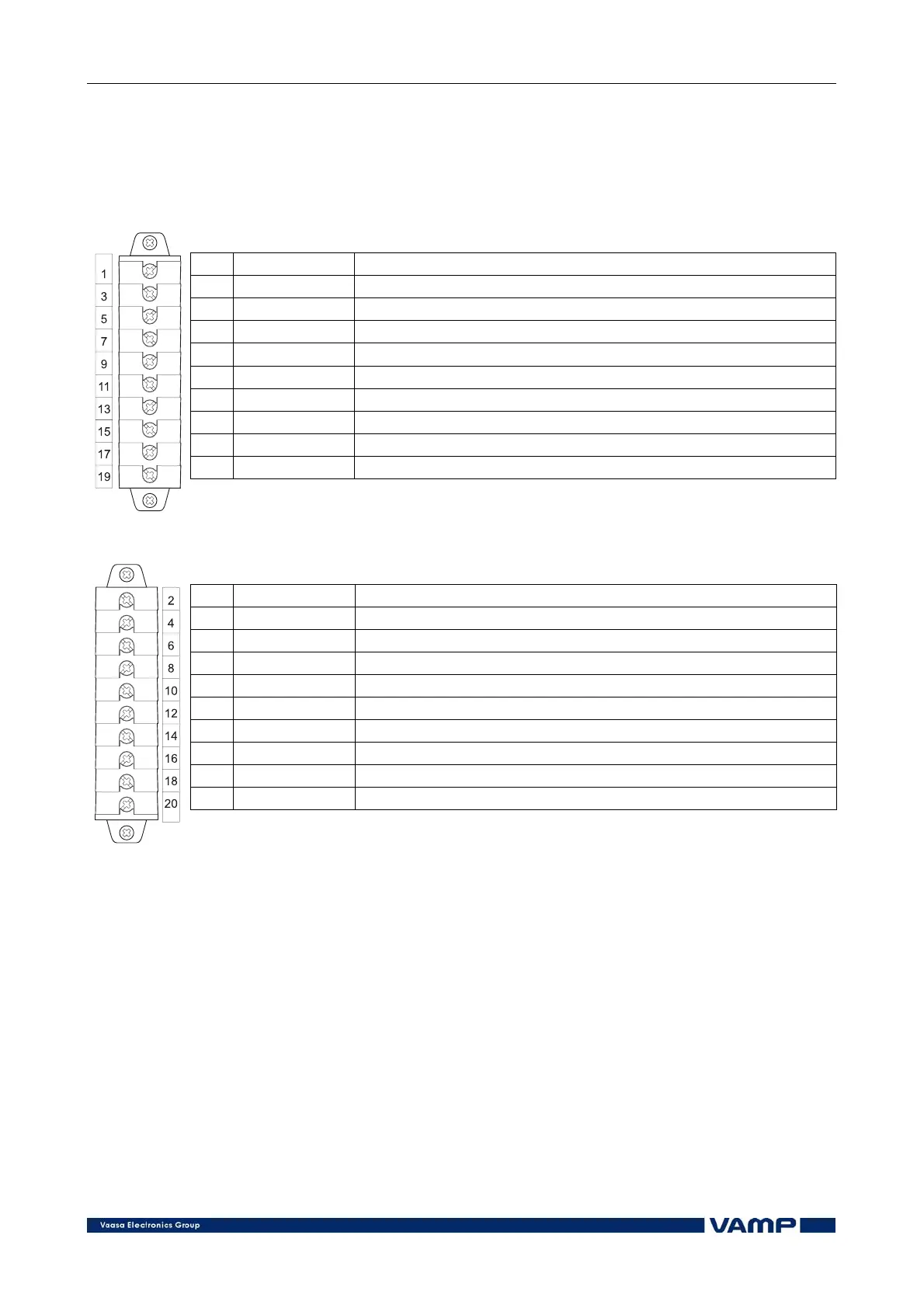
The feeder and motor manager VAMP 257 is connected to the
protected object through the following measuring and control
connections:
Terminal X1 left side
No: Symbol Description
1 IL1(S1) Phase current L1 (S1)
3 IL2(S1) Phase current L2 (S1)
5 IL3(S1) Phase current L3 (S1)
7 Io1/1A(S1) Residual current Io1(S1)
9 Io2/5A(S1) Residual current Io2(S1)
11 UL1(a)/U12 Phase to earth voltage L1 (a) or phase to phase voltage U12
13 UL2(a)/U23 Phase to earth voltage L2 (a) or phase to phase voltage U23
15 -- --
17 UL3(a)/Uo(dn) Phase to earth voltage L3 (a) or residual voltage Uo(dn)
19 -- --
Terminal X1 right side
No: Symbol Description
2 IL1(S2) Phase current L1 (S2)
4 IL2(S2) Phase current L2 (S2)
6 IL3(S2) Phase current L3 (S2)
8 Io1/1A(S2) Residual current Io1 (S2)
10 Io2/5A(S2) Residual current Io2 (S2)
12 UL1(n)/U12 Phase to earth voltage L1 (n) or phase to phase voltage U12
14 UL2(n)/U23 Phase to earth voltage L2 (n) or phase to phase voltage U23
16 -- --
18 UL3(n)/Uo(da) Phase to earth voltage L3 (n) or residual voltage Uo(da)
20 -- --