VAMP 257 Feeder and motor manager
Technical description
VAMP Ltd
8
VAMP 24h support phone : +358 (0)20 753 3264
VM257.EN002
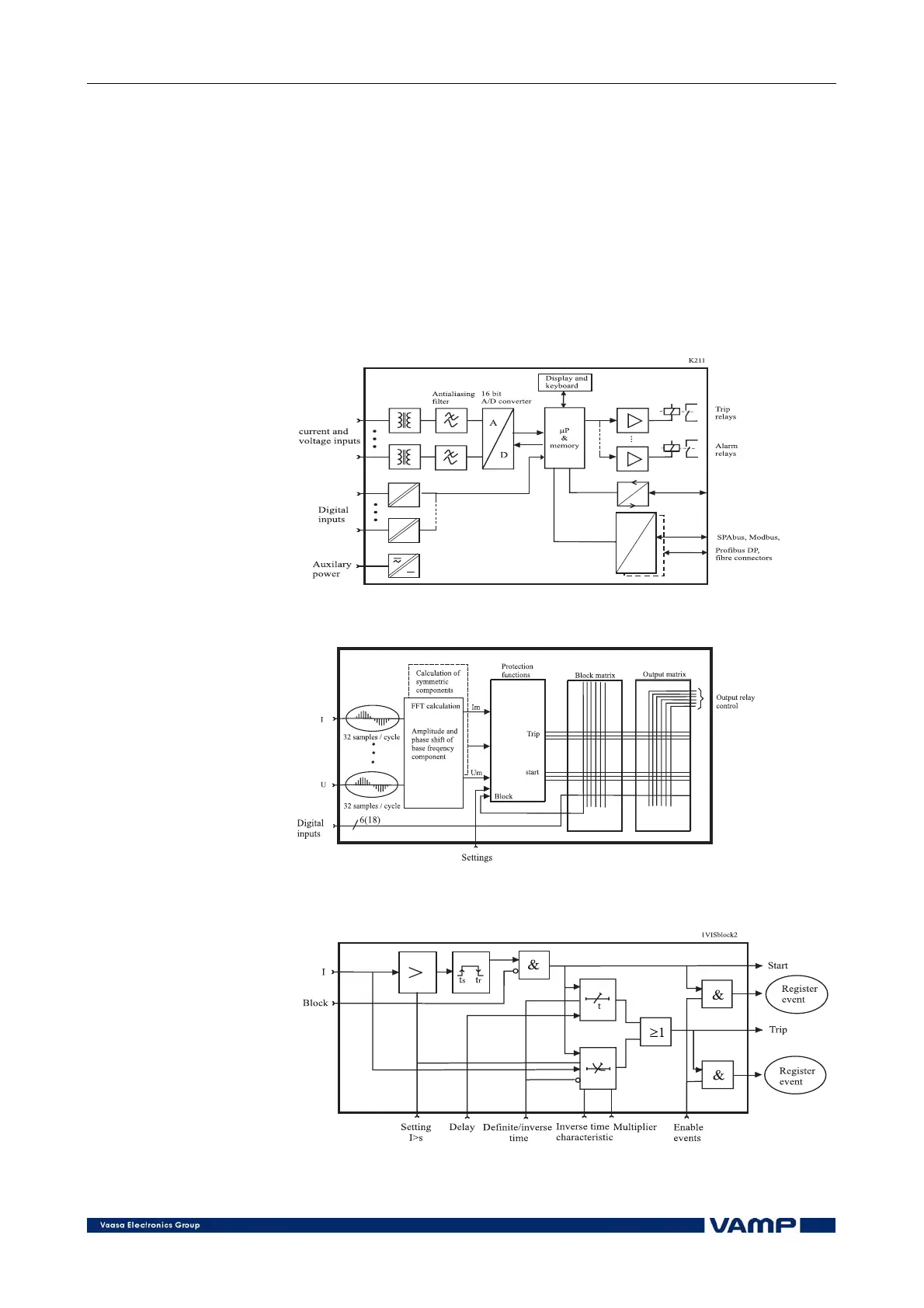
Figure 2.1-1 shows a principle block diagram of a numerical
manager. The main components are the energizing inputs,
digital input elements, output relays, A/D converters and the
micro controller including memory circuits. Further, a manager
contains a power supply unit and a human-machine interface
(HMI).
Figure 2.1-2 shows the heart of the numerical technology. That
is the main block diagram for calculated functions.
Figure 2.1-3 shows a principle diagram of a single-phase
overvoltage or overcurrent function.
Figure 2.1-1. Principle block diagram of a numerical feeder manager
Figure 2.1-2. Block diagram of a software based protection function
Figure 2.1-3. Block diagram of a single phase protection function