VAMP 257 Feeder and motor manager
Technical description
VAMP Ltd
14
VAMP 24h support phone : +358 (0)20 753 3264
VM257.EN002
Limitations:
The maximum measured secondary current is 250 A. This
limits the scope of inverse curves when the setting is more than
12.5 A.
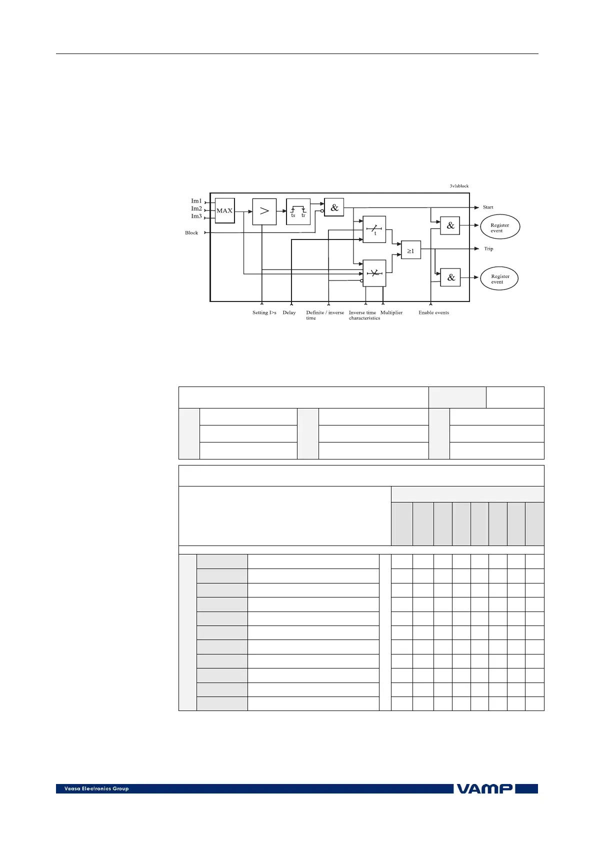
Figure 2.3.1-1 shows a functional block diagram of the I> stage
of the overcurrent function.
Figure 2.3.1-1. Block diagram of the three-phase overcurrent stage I>
Setting parameters of overcurrent stages:
I>, I>>, I>>> (50/51)
Pickup setting Unit:
xI
mode
I> 0.10 ... 5.00 1.20
I>> 0.10 … 20.00 2.50
Param.
I>>>
Range
0.1 … 40.00
Default
5.00
Operation delay selection (only for I>)
Curve
Curve
Type
A…E
- curve family selection
- delay type selection
- formula parameters
DT
IEC
IEEE
IEEE2
RI
Prg1
Prg2
Prg3
DT
Definite time
X
NI
Normal inverse
X X
VI
Very inverse
X X X
EI
Extremely inverse
X X X
LTI
Long time inverse
X X
LTEI
Long time extremely inverse
X
LTVI
Long time very inverse
X
MI
Moderately inverse
X X
STI
Short time inverse
X
STEI
Short time extremely inverse
X
Type
RI
X