VAMP Ltd Feeder and motor manager
Technical description
VAMP 257
VM257.EN002 VAMP 24h support phone : +358 (0)20 753 3264
17
Measured and recorded values of overcurrent stages:
I>, I>>, I>>> (50/51)
Parameter Values Unit Description
Measured
value
ILmax A
Corresponding primary
value
SCntr Cumulative start counter
TCntr Cumulative trip counter
1-N, 2-N,
3-N
Fault type/single-phase
fault e.g.: 1-N = fault on
phase L1
1-2, 2-3,
1-3
Fault type/two-phase fault
e.g.: 2-3 = fault between L2
and L3
Type
1-2-3
Fault type/three-phase
fault
Flt xImode
The max. value of fault
current as compared to In
Load A
1 s mean value of pre-fault
phase currents IL1…IL3
Recorded
values
Edly %
Elapsed time as compared
to the set operating time,
100% = tripping
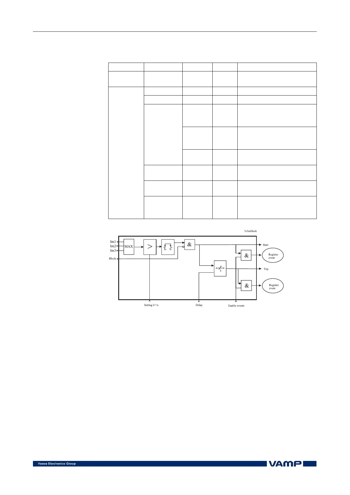
Figure 2.3.1-2. Block diagram of the three-phase overcurrent stage I>>