VAMP Ltd Feeder and motor manager
Technical description
VAMP 257
VM257.EN002 VAMP 24h support phone : +358 (0)20 753 3264
23
there is a sudden increase in the phase currents (e.g. short-
circuit).
3. Phase currents and voltages are registered in three stages:
before the fault, during the fault and after the faulty feeder
circuit-breaker was opened.
4. The fault distance quantities are calculated.
5. Two phases with the biggest fault current are selected.
6. The load currents are compensated.
7. The faulty line length reactance is calculated.
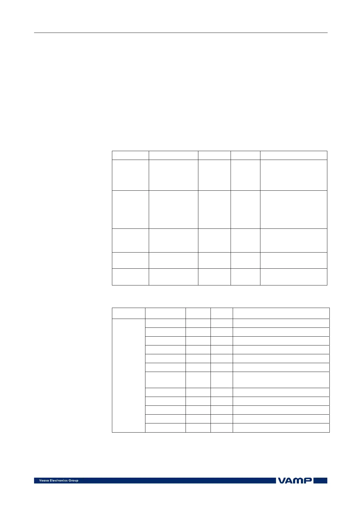
Setting parameters of fault location:
Dist
Parameter Value Unit Default Description
Trig dI;
DI1 … DI32
- -
Trigger mode (dI=
triggering based on
sudden increase of
phase current)
Line
reactance
0.010 … 10.000 Ohms/km 0.378
Line reactance of the
line. This is used only
to convert the fault
reactance to
kilometres.
dItrig 5 … 800 % Imode 20
Trig current (sudden
increase of phase
current)
Kd 0.00 … 1.00 - 0.31
Load distribution
factor
Event Disabled;
Enabled
- Enabled Event mask
Measured and recorded values of fault location:
Dist
Parameter Value Unit Description
Distance km Distance to the fault
Xfault ohm Fault reactance
Date - Fault date
Time - Fault time
Time ms Fault time
Cntr - Number of faults
Pre A
Pre-fault current (=load
current)
Fault A Current during the fault
Post A Post-fault current
Udrop %Un Voltage dip during the fault
Durati s Fault duration
Measured
values/
recorded
values
Xfault ohm Fault reactance