VAMP Ltd Feeder and motor manager
Technical description
VAMP 257
VM257.EN002 VAMP 24h support phone : +358 (0)20 753 3264
29
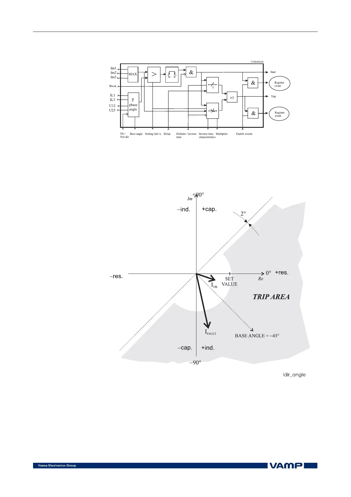
Figure 2.3.4-1 shows a functional block diagram of the I
dir
>
stage of the directional overcurrent function.
Figure 2.3.4-1. Block diagram of the three-phase overcurrent stage I
dir
>
The following figure shows an example of directional
overcurrent angle characteristics. The base angle setting is set
to -45º. The stage will trip when the tip of the current phasor is
in the grey area.
Figure 2.3.4-2. Example of directional overcurrent angle characteristics