VAMP Ltd Feeder and motor manager
Technical description
VAMP 257
VM257.EN002 VAMP 24h support phone : +358 (0)20 753 3264
43
Inverse time multiplier
0.05 ... 20.00
(IEC)
(IEEE)
(IEEE2)
Param.
K
Range
0.5 … 20.00
(RI)
Default
1.0
Event enabling Range:
Enabled/disabled
S_On
Start on event
Enabled
S_Off
Start off event
Enabled
T_On
Trip on event
Enabled
Param.
T_Off
Trip off event
Default
Enabled
Limitations:
The maximum measured secondary current is 10 A for input
signal I
0
, 50 A for input signal I
02
and 250 A for calculated
signal I
0Calc
. This limits the scope of inverse delays if the setting
is more than the maximum measured current divided by 20.
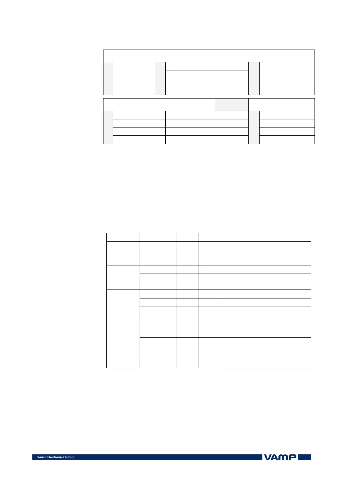
Measured and recorded values of directional earth fault
protection:
I
0
ϕ>, I
0
ϕ>> (67N)
Parameter Value Unit Description
IoRes/Cap A
Primary (Res/Cap) earth fault
current Io
Measured
values
Uo % Residual voltage Uo
Ioϕ>, Ioϕ>>
A Setting value as primary value
Display
Char Res;
Cap
Actual operation characteristic
(Res=Resistive; Cap=Capacitive)
SCntr Cumulative start counter
TCntr Cumulative trip counter
Flt pu Max. fault current
EDly %
The elapsed time compared to
the set operating time; 100% =
tripping
Angle o
Phase angle between residual
voltage and current
Recorded
values
Uo %
The max. residual voltage under
fault condition