SECTION 6: MAINTENANCE AIR N ARC
®
200 SERIES ALL-IN-ONE POWER SYSTEM
®
PAGE - 80 090019-OP_r0
2. Remove the ten (10) truss head screws and
washer pairs securing the belt guard to the
frame.
3. Remove the shield and place it in a safe
location.
6.5.7.2 REPLACING THE BELT GUARD SHIELD
After the belts have been serviced, the belt guard must
be secured back into position before the operating the
machine. To re-secure the belt guard, refer to Figure 6-9,
follow these instructions:
1. Align the shield’s holes with the holes in the
frame.
2. Secure the shield to the frame by placing a
truss head screw through a nylon washer,
and hand-tightening each pair until all ten
(10) pairs are securing the guard into place.
3. Tighten all screws with a screw driver or drill
bit driver.
4. Reconnect the ground wire to the battery.
5. Log any maintenance entry into the
Maintenance and Service Log found in
Appendix B.
6.5.7.3 RE-TENSIONING THE AIR COMPRESSOR
DRIVE BELT(S)
The poly-link v-belts used for the compressor drive do
not require a separate tensioner. Rather, the belts are
directly sized by the amount of links in the belt. Proper
tension on a poly-link v-belt is 3/8” to 1/2” give (see
Figure 6-10). Consult Figures 6-9, 6-10, 6-11, and the
following procedure:
1. With the machine off and the ground wire
disconnected from the battery, remove the
belt guard shield per Section 6.5.7.1.
TOOLS/ITEMS NEEDED
REPLACEMENT
PART(S)
Large Phillips Head Screw
Driver or Drill Bit & Drill
Not Applicable
TOOLS/ITEMS NEEDED
REPLACEMENT
PART(S)
Optional Long-Nosed Pliers Compressor
Drive Belt No.
DR270814 (2)
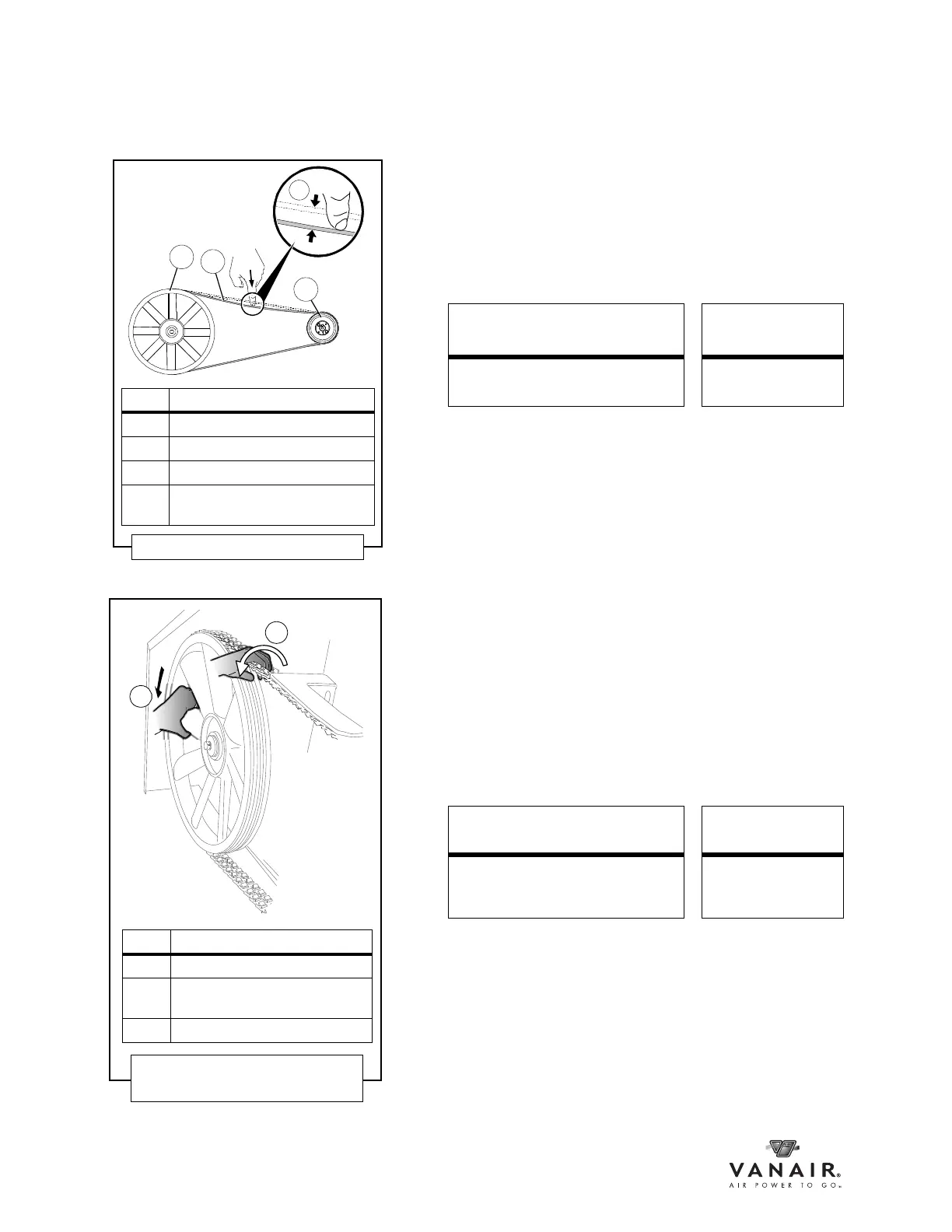
KEY DESCRIPTION
A COMPRESSOR PULLEY
B DRIVE V-BELT
C ENGINE PULLEY
D BELT DEFLECTION RANGE:
3/8 to 1/2 inch
Figure 6-10: Belt Deflection
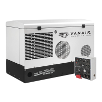
KEY DESCRIPTION
A COMPRESSOR PULLEY
B BELT DEFLECTION RANGE:
3/8 to 1/2 inch
C ENGINE PULLEY
Figure 6-11: Removing the
Compressor Belt(s)