SECTION 5: OPERATION AIR N ARC
®
200 SERIES ALL-IN-ONE POWER SYSTEM
®
PAGE - 46 090019-OP_r0
5.4.1 WELDER OPERATING PROCEDURE
5.4.1.1 CC (CONSTANT CURRENT) MODE
CC (Constant Current) Mode is commonly referred to as -
Stick Welding, Arc Welding, or Shielded Metal Arc
Welding (SMAW)
1. With the engine shut off, insert the twist lock
connections of the ground clamp and the
electrode holder cables into the welder
connection ports on the control panel. For
Direct Current Electrode Positive (DCEP)
connect the electrode holder to the positive
(+) port, and the ground clamp to the
negative (–) port. For Direct Current
Electrode Negative (DCEN) connect the
electrode holder to the negative (–) port, and
the ground clamp to the positive (+) port.
2. Select the appropriate electrode for the
material and process being performed. See
Table 5B for selecting an electrode.
3. Place the ground clamp on the work piece
and insert the appropriate welding rod into
the electrode clamp.
4. Start the engine (See Section 5.2, Engine
Start-up and Shutdown Procedure).
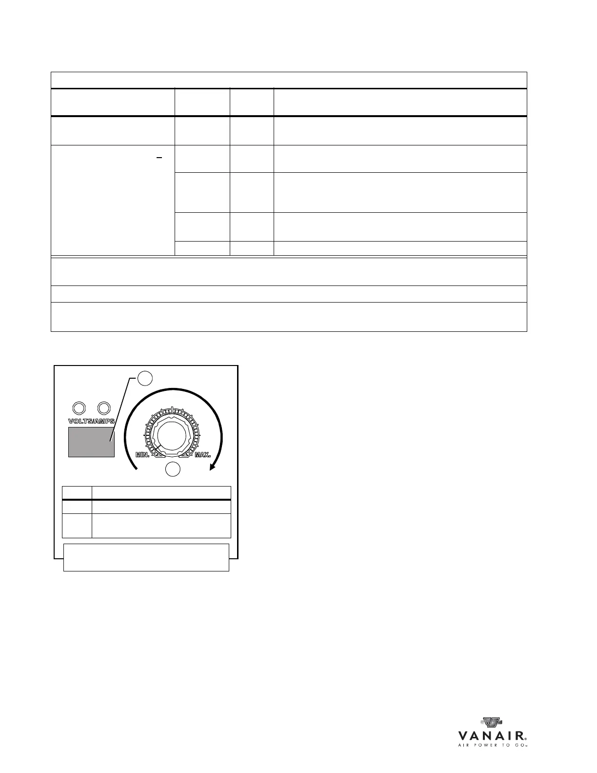
TABLE 5A: ENGINE THROTTLE CONTROL FUNCTION CONDITIONS
I
Air Pressure Generator
Switch
Welder
Switch
Engine Speed Condition Result
Tank Pressure Below (<)
150 PSI or Set Pressure
II
OFF OFF Engine runs at full throttle (3600 RPM).
Tank Pressure Above (>
)
150 PSI or Set Pressure
II
OFF OFF Engine runs at idle speed (2000 RPM), ready for
application.
OFF ON Welder can be activated by striking an arc, and Engine runs
at idle speed (2000 RPM) unless CV Mode, ready for
application.
ON OFF Engine runs at full throttle speed (3600 RPM); generator is
ready for use
III
.
ON ON Full speed and all items available for use.
I
Any combination of the 200 Power System output functions (compressor, generator, welder) used
simultaneously at capacity will have an adverse affect on engine running at full throttle.
II
Factory set pressure: 150 PSI = ON / 175 PSI = OFF
III
Consult Appendix A, Section A.3, Wattage Requirements for Common Receptacle Units for a listing of
wattage requirements of various implements.
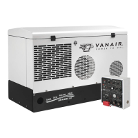
KEY DESCRIPTION
A DIGITAL READ OUT DISPLAY
B RANGE:
30-205 AMPS / 15-40 VOLTS
Figure 5-3: Variable Power Dial
Adjustment