AIR N ARC
®
200 SERIES ALL-IN-ONE POWER SYSTEM
®
SECTION 6: MAINTENANCE
090019-OP_r0 PAGE - 83
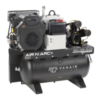
4. Push down on the tab [F], while pulling up on
the link’s end [G].
6.5.7.6 COMPRESSOR BELT ASSEMBLY
Once the proper length of the belt has been determined
(refer to Section 6.5.7.4), and the belt is shortened to its
proper fitted length (refer to Section 6.5.7.5), then the
belt’s ends are linked together to form the completed belt.
Refer to Figure 6-14, and the following procedure:
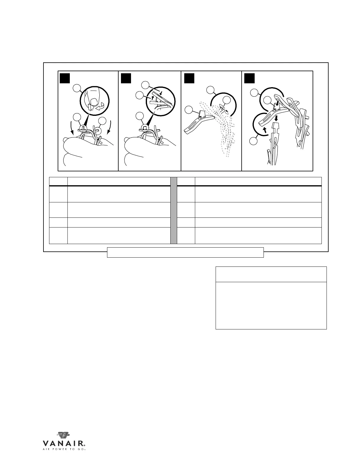
1. Place tab [A] corner against the inside of the
link hole [B] (nearest to thumb [D]).
2. With thumb [C], push on the tab’s edge in the
direction indicated.
3. Simultaneously with Step #2 above, push on
link end [B] with thumb [D] in the direction
indicated. NOTE: Inset [E] shows how the
pressure applied from both thumbs causes
the tab to “rotate” toward the slot position.
KEY DESCRIPTION KEY DESCRIPTION
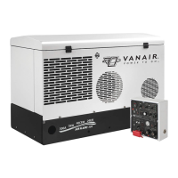
A
Rotate tab [B
1
] 90° so that the tab’s end
is parallel to the slot it is linked to
D Pull up on link end while pushing down on [C]
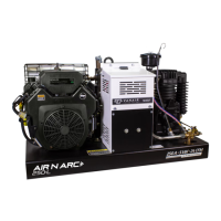
B
1
First tab to unlink E Rotate belt end with tab [B2] 90° so that the tab’s
end is parallel to the slot it is linked to
B
2
Second tab to unlink F Push down on the tab [B
2
], while pulling up on [G]
C Push down on the tab [B
1
], while pulling
up on [D]
G Pull up on link end while pushing down on [C]
Figure 6-13: Compressor Drive V-Belt - Link Removal
B
1
B
2
A
1 2 3 4
B
2
B
1
B
1
E
B
2
F
G
C
D
NOTE
To completely disconnect excess links
from a belt, two adjacent tabs will need to
freed to disengage the link.
In Figure 6-13, Tab [B
1
] represents the
first tab, and Tab [B
2
] represents the
second tab.