AIR N ARC
®
200 SERIES ALL-IN-ONE POWER SYSTEM
®
SECTION 6: MAINTENANCE
090019-OP_r0 PAGE - 97
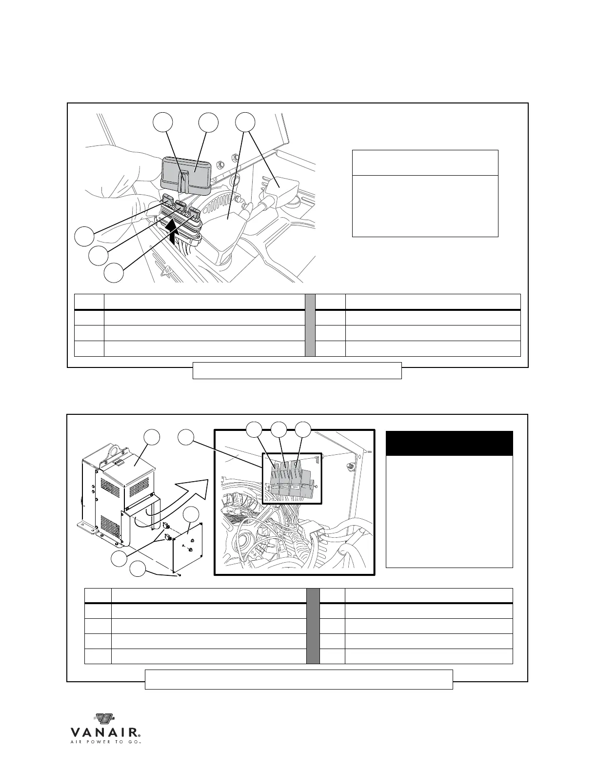
KEY DESCRIPTION KEY DESCRIPTION
A BATTERY CABLE CONNECTIONS (reference) D 5 AMP FUSE - Generator Switch
B FUSE HOLDER LID E 10 AMP FUSE - Start
C FUSE HOLDER LID MOUNTING GROOVE F 15 AMP FUSE - DC Welder Generator
Figure 6-25: Power System Fuses
NOTE
Replacement fuses can
sometimes be found at local
vendor carriers, such as
automobile supply stores,
hardware stores, etc.
KEY DESCRIPTION KEY DESCRIPTION
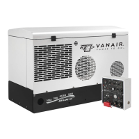
A CANOPY - Generator(s) and Battery Housing E RELAYS
B CIRCUIT BREAKERS E1 AC GENERATOR
C FACEPLATE E2 SWITCHED POWER
D PHILLIPS PAN HEAD SCREW (x 4) E3 POWER
Figure 6-26: AC Generator - Breaker and Relay Locations
IMPORTANT
The instrument panel
internal wiring is snugly fit
and ordered within the box.
If the panel has to be
accessed to replace the
breakers, pull the face plate
away from the box very
carefully, and only as far as
needed to access the
breakers.
 Loading...