AIR N ARC
®
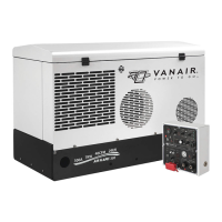
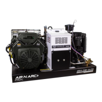
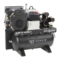
200 SERIES ALL-IN-ONE POWER SYSTEM
®
SECTION 2: DESCRIPTION
090019-OP_r0 Page - 21
FIGURE 2-1: MAJOR MACHINE COMPONENTS LOCATIONS KEY
KEY DESCRIPTION
A INSTRUMENT PANEL
A
1
SERVICE AIR OUTLETS
I
B LIFTING BAIL
C FUEL FILL (Remote Mount)
D ENGINE AIR FILTER
E MUFFLER
F ENGINE OIL FILL PORT
G ENGINE OIL FILTER
H ENGINE OIL DRAIN
J PRESSURE SWITCH
K PILOT VALVE
L
AC GENERATOR CIRCUIT BREAKERS (25 Amp)
II
M HIGH PRESSURE VALVE
N LOW PRESSURE VALVE
P COMPRESSOR AIR FILTER
Q COMPRESSOR UNIT
R OIL SIGHT GLASS
S COMPRESSOR OIL DRAIN PORT (Plugged)
T DC GENERATOR
U AC GENERATOR
V COMPRESSOR PULLEY/FLYWHEEL
W COMPRESSOR BELT (x 2, Adjacent)
X GENERATOR BELT
Y GENERATOR IDLER/ADJUSTMENT SHEAVE
Z ENGINE PULLEY
I
These service valve locations are auxiliary; main service valve outlet may also be located at base access
[A
2
], or as per customer installation.
II
For additional locations of other system fuses or circuit breakers, consult Section 6.6, Servicing the Sys-
tem Fuses and Circuit Breakers.
NOTE
Refer to Section 9, Illustrations and Parts
List, for assembly details and
corresponding part numbers.